Introduction
Internet Of Things (IoT) – The Internet of Things seems to be in the forefront of a modern, civilized world. It’s a scenario where everything can be connected via the wireless Internet. Businesses are increasingly adopting IoT technology into production because of the potential market for innovation and lower production costs.
Seeing the fast-paced development of IoT technology products and the potential start-up technology market, this book provides IoT content with a coherence, fact, towards young people who have been and want to focus their energies on the Internet of Things. Desire to create unique products, creative, increasingly perfect and synchronized to meet the needs of life.
The content is designed essentially to give students an overview of system construction, equipment production and easy access to the IoT.
About author
The author of book is a Mr. Phạm Minh Tuấn(TuanPM), he has many years of experience working in the IoT and developing the open source library for the community. He wants to share a little of his knowledge to the development very potential this industry.
Terminology used
-
IoT- Internet Of Things. -
ESP8266- Wi-Fi microcontroller. -
Git- version control system . -
Github- A social network for developer based on Git. -
IDE- Integrated Development Enviroment. -
Compiler- A software program that transforms high-level source code that is written by a developer in a high-level programming language into a low level object code (binary code) in machine language. -
Logic Level- The voltage level for the chip to understand (1 or 0).
Explain the source code
void setup()
{
    //comment (1)
    int a = 1;
    a ++; (2)
}| 1 | This line explains this as a comment. |
| 2 | This line explains the variable a which adds 1 unit. |
Introduction to contents
The contents of this book include detailed instructions for IoT application developers using the popular WiFi chip ESP8266, to connect to the server, send and receive data, and execute commands from the server. Internet Of Things depends on the Internet connection, so the content is also focused on protocols, management methods as well as connection configuration.
The main hardware used is System On Chip (SoC). ESP8266 - WiFi and programmable with cheap price and popular in the world. The circuit board used is the hardware open. IoT WiFi Uno has a legacy mapping board compatible with Arduino Uno.
The software used on the computer for the ESP8266 chip is Arduino, the C/C++ programming language.
The parts related to Server running on the computer use NodeJS and Javascript programming.
In addition, you will need to learn some of the tools and concepts that are frequently used in this book:
-
Git - is a version control system for tracking changes in computer files and coordinating work on those files among multiple people, Github is a social network for developer based on Git. Git helps you manage source code, group work, merge operations, source code history … Probably in the process of working with this book, you will need to use open source libraries for Arduino from Github, so the installation and use of the tool is quite necessary for that. It will help you manage the source code and project more and more professional.
-
Sublime Text - A popular, fast, lightweight and feature rich editÚe Use for programming. Javascript (NodeJS)
-
Code formater - Used to format the source code, easy to read, easy to repair.
-
Editorconfig - An additional tool for the Editor, which helps to synchronize standards such as Indent, Align, Space … to ensure that code is opened in the Editor is not changed.
Although the official hardware is hardware open IoT WiFi Uno, but you can use any board ESP8266 on the market for this book, eg: NODEMCU,` Wemos`, …
|
| The content in this book focuses on protocol guidance, how to work with systems using ESP8266, Server …, and sample projects. |
| All Code sections do not explain the API details for each feature. Instead, it is provided in the Appendix Cheat Sheet (Arduino and C). |
Who can use?
-
Software developers / Mobile App, Web App …the person who wants to participate as
IoTproducts. -
Students want to improve their skills and additional knowledge.
-
Individuals want to make their own products for life, serving the work.
-
Startup Tech does not specialize in hardware or software.
Target of this book
-
Help for non-hardware approach to make the product easy IoT.
-
Can be integrated system development for IoT products.
-
Understanding the process of creating hardware products, go into the production of equipment.
-
Avoid unnecessary errors when developing and designing the system.
Preparation
-
You need a programmable ESP8266 board, it is best to use a board that is compatible with the Arduino IDE (which has modules for the chip).
-
There should be additional modules such as sensors, motors to practice, a set of StarterKit is suitable.
-
1 personal computer (Windows, MacOS or Linux).
-
C & Arduino ESP8266 Cheatsheet (Contents at the end of this book).
- Introduction
- Introduction to contents
- Basic knowledge
- Hello World
- ESP8266 WiFi
- Temperature and Humidity Monitor using DHT11, ESP8266 and Node.js server
- WiFi configuration on ESP8266
- MQTT
- Summary:
- Websocket
- Firmware update over the air (FOTA)
- Cheatsheet
- The ending
Basic knowledge
In this chapter, we start off with an overview of IoT system, ESP8266 product line, and then how to set up a Arduino working environment on your computer. Next we proceed to some sample programs, which library to use. After this chapter, you will have a general view on an IoT system, and grapse how to use the tools necessary for prgramming ESP8266
A quick look at the chapter:
-
IoTand pratical applications. -
Get to know
ESP8266WiFi chip. -
Arduino IDEusing Arduino with ESP8266. -
Starter Kit, anIoTstarter kit. -
Node.js - Javascript, server-side programming language. -
Installingall necessary tools.
Those who are familiar with ESP8266, have worked with an IoT system, or are proficient in C/C++ programming can skip this part.
Internet Of Things (IoT)
What is Internet of Things (IoT)?
Internet of Things (IoT) - The Internet of things is the network of physical devices, vehicles, home appliances, and other items embedded with electronics, software, sensors, actuators, and network connectivity which enable these objects to connect and exchange data. Each thing is uniquely identifiable through its embedded computing system but is able to inter-operate within the existing Internet infrastructure. Link: en.wikipedia.org/wiki/Internet_of_things
Internet of Things (IoT) refers to objects that can be identified as well as their existence in a connected, interconnected architecture: a network of things connected to the Internet, or simply Things.
IoT can be a sensor that is assembled in a refrigerator to record temperature, is a heart transplanted in the human body,…Understandably, IoT makes things easier to communicate with each other The biggest advantage of smart is the ability to prevent and warn anywhere.
The term "the Internet of things" was coined by Kevin Ashton of Procter & Gamble, later MIT’s Auto-ID Center, in 1999, after that, it was used extensively in publications by manufacturers and analysts. They identified IoT as a complex system, because it contains many connections between machines, equipment and services. Initially, IoT was not meant to be automatic and intelligent. Later, it was thought to combine the two concepts IoT - Autonomous control together. It can observe change and feedback with the surroundings, also can control itself without network connection. Integrating intelligence into IoT can also help devices, machines and software collect and analyze human electronic data when we interact with them. In the future, people will be able to communicate with machines via wireless internet without any additional intermediaries.
The question is, what helps IoT "smart" and "understand" people? Initially, people thought that the Internet of things was primarily about M2M communication (devices connected via another device). But when it comes to "intelligence", It’s not just M2M communication that we need to mention the sensors. And do not be mistaken that the Sensor is a machine that operates under the control of other devices that are essentially similar to human eyes and ears with continuous recognition of measurements. After all, Internet of Things provides a connection between machines and sensors, and the cloud data to encrypt data. Cloud computing applications are the key to making Internet of Things work by analyzing, processing and using the data the sensors collect.
In the world today, the impact of the IOT is diverse and active in many areas: infrastructure management, health, construction and automation, transportation …. John Chambers (CEO of Cisco) announced: By 2024 there will be 500 billion connected devices. In fact, this number is nearly 100 times greater than the number of people on Earth, That shows that things are more than people very much. We all know the IoT application can talk to people through the keyboard, and the device is also designed with more and more sensors to communicate in the fastest and most accurate way, it help to collect simple data from each of us. But most importantly, although it communicates with humans, the IoT application is not human.
The people said that IoT is the key to success, it is the turning point and great opportunity of the future. In order not to fall behind, governments and businesses need to innovate and invest more aggressively in developing products that apply Internet of things technology.
The hashtag: #IoT #InternetOfThings
Internet of Things(IoT) system
IoT systems allow users to achieve deeper automation, analysis, and integration within a system. They improve the reach of these areas and their accuracy. IoT utilizes existing and emerging technology for sensing, networking, and robotics.
IoT exploits recent advances in software, falling hardware prices, and modern attitudes towards technology. Its new and advanced elements bring major changes in the delivery of products, goods, and services; and the social, economic, and political impact of those changes.
IoT − Key Features
The most important features of IoT include artificial intelligence, connectivity, sensors, active engagement, and small device use. A brief review of these features is given below:
-
AI (Artifical Intelligence) - H IoT essentially makes virtually anything “smart”, meaning it enhances every aspect of life with the power of data collection, artificial intelligence algorithms, and networks. This can mean something as simple as enhancing your refrigerator and cabinets to detect when milk and your favorite cereal run low, and to then place an order with your preferred grocer.
-
Connectivity - New enabling technologies for networking, and specifically IoT networking, mean networks are no longer exclusively tied to major providers. Networks can exist on a much smaller and cheaper scale while still being practical. IoT creates these small networks between its system devices.
-
Sensors - IoT loses its distinction without sensors. They act as defining instruments which transform IoT from a standard passive network of devices into an active system capable of real-world integration.
-
Active Engagement Much of today’s interaction with connected technology happens through passive engagement. IoT introduces a new paradigm for active content, product, or service engagement.
-
Small Devices - Devices, as predicted, have become smaller, cheaper, and more powerful over time. IoT exploits purpose-built small devices to deliver its precision, scalability, and versatility.
IoT − Advantages
The advantages of IoT span across every area of lifestyle and business. Here is a list of some of the advantages that IoT has to offer:
-
Improved Customer Engagement - Current analytics suffer from blind-spots and significant flaws in accuracy; and as noted, engagement remains passive. IoT completely transforms this to achieve richer and more effective engagement with audiences.
-
Technology Optimization - The same technologies and data which improve the customer experience also improve device use, and aid in more potent improvements to technology. IoT unlocks a world of critical functional and field data.
-
Reduced Waste - IoT makes areas of improvement clear. Current analytics give us superficial insight, but IoT provides real-world information leading to more effective management of resources.
-
Enhanced Data Collection - Modern data collection suffers from its limitations and its design for passive use. IoT breaks it out of those spaces, and places it exactly where humans really want to go to analyze our world. It allows an accurate picture of everything.
IoT − Disadvantages
Though IoT delivers an impressive set of benefits, it also presents a significant set of challenges. Here is a list of some its major issues:
-
Security - IoT creates an ecosystem of constantly connected devices communicating over networks. The system offers little control despite any security measures. This leaves users exposed to various kinds of attackers.
-
Privacy - The sophistication of IoT provides substantial personal data in extreme detail without the user’s active participatSome find IoT systems complicated in terms of design, deployment, and maintenance given their use of multiple technologies and a large set of new enabling technologies.
-
Flexibility - Many are concerned about the flexibility of an IoT system to integrate easily with another. They worry about finding themselves with several conflicting or locked systems.
-
Compliance - IoT, like any other technology in the realm of business, must comply with regulations. Its complexity makes the issue of compliance seem incredibly challenging when many consider standard software compliance a battle.
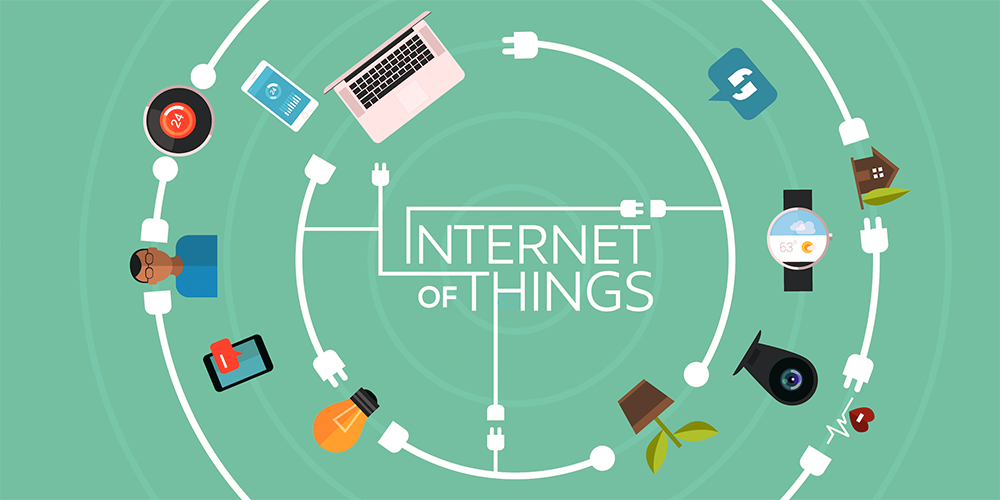
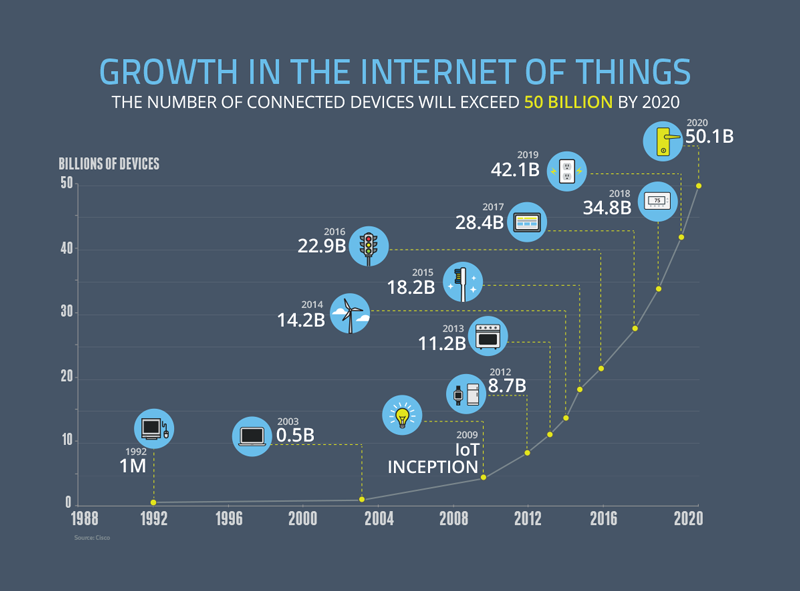
Real World Applications of Internet of Things
To help clarify how the Internet of Things works, we’ve laid out some applications for the IoT, along with some specific devices and examples:
-
Smart Home - According to statistics, smart home is the most searched IoT related applications on Google search. Smart Home is a home with lots of automatic features such as turn on the air-conditioner when you’re about to go home, turn off the lights when you leave the house, unlocking when your family member is at your door, Open the garage when you drive home from work… and other features that help improve the quality of life when using smart home.
-
Wearables - Some of the devices, like the
Dashbon Mask, this is a smart headphone. It’s help you listen to high quality music and watch HD movies with the virtual projector, orAMPL SmartBaga backpack with reserve cell that can charge for mobile devices, computers.. -
Connected cars - Help improve the quality of service for car users, a
Connected carcan optimize its operations such as reporting when low on fuel, giving alerts when things are approaching or most recently Tesla’s self-driving electric car…
ESP8266
ESP8266 is a cheap WiFi 2.4Ghz compatible SoC which is manufactured by a Chinese semiconductor company: Espressif Systems.
It was initially designed in August 2017, packed in a ESP-07 module which was manufactured by a third-party: AI-Thinker. It comes with the ability to connect to the Internet through WiFi network with decent speed, consumes little energy and requires less external components. ESP8266 has a good ratio of cost to performance.
ESP8266 now has a large community worldwide, providing various modules bundled with open source codes, which are user-friendly and cut time-to-market.
At the time of writing, ESP8266EX is the standard in the ESP8266 family.
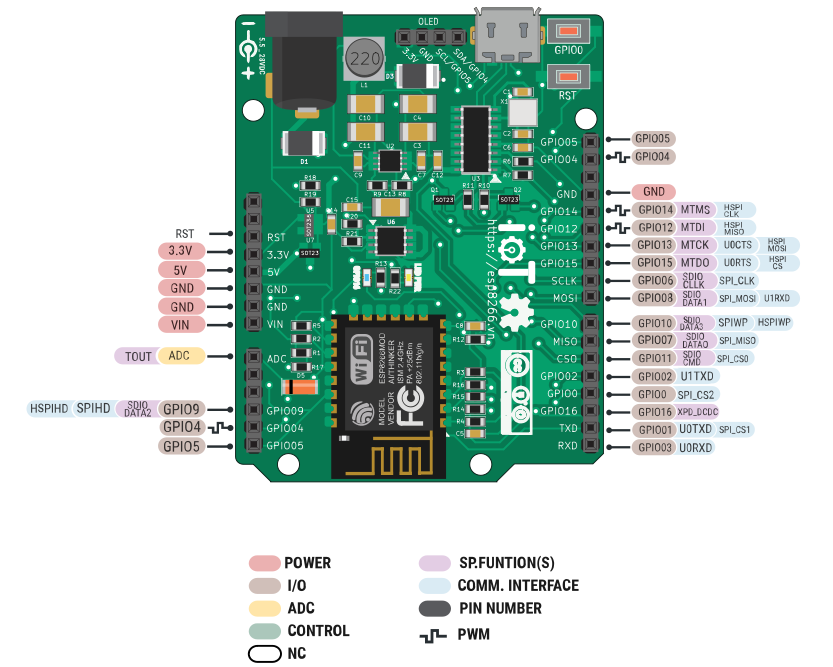
Pin mapping
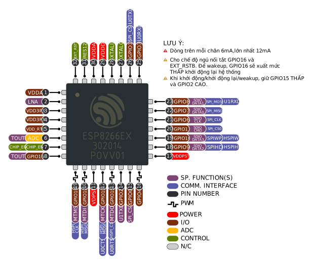
Hardware description
-
32-bit RISC CPU : Tensilica Xtensa LX106 running at 80 MHz
-
Support for external Flash of 512KiB to 4MiB
-
64KBytes RAM for instructions
-
96KBytes RAM for data
-
64KBytes boot ROM
-
EEE 802.11 b/g/n, Wi-Fi 2.4 GHz compatible
-
Integrate TR switch, balun, LNA, Power Amplification and Matching network
-
Support for WEP, WPA/WPA2, Open network
-
-
Integrate TCP/IP
-
Support for many types of antennae
-
16 GPIO pins
-
SDIO 2.0, UART, SPI, I²C, PWM,I²S with DMA.
-
1 ADC 10-bit
-
Operating Temperature Range : -40C ~ 125C
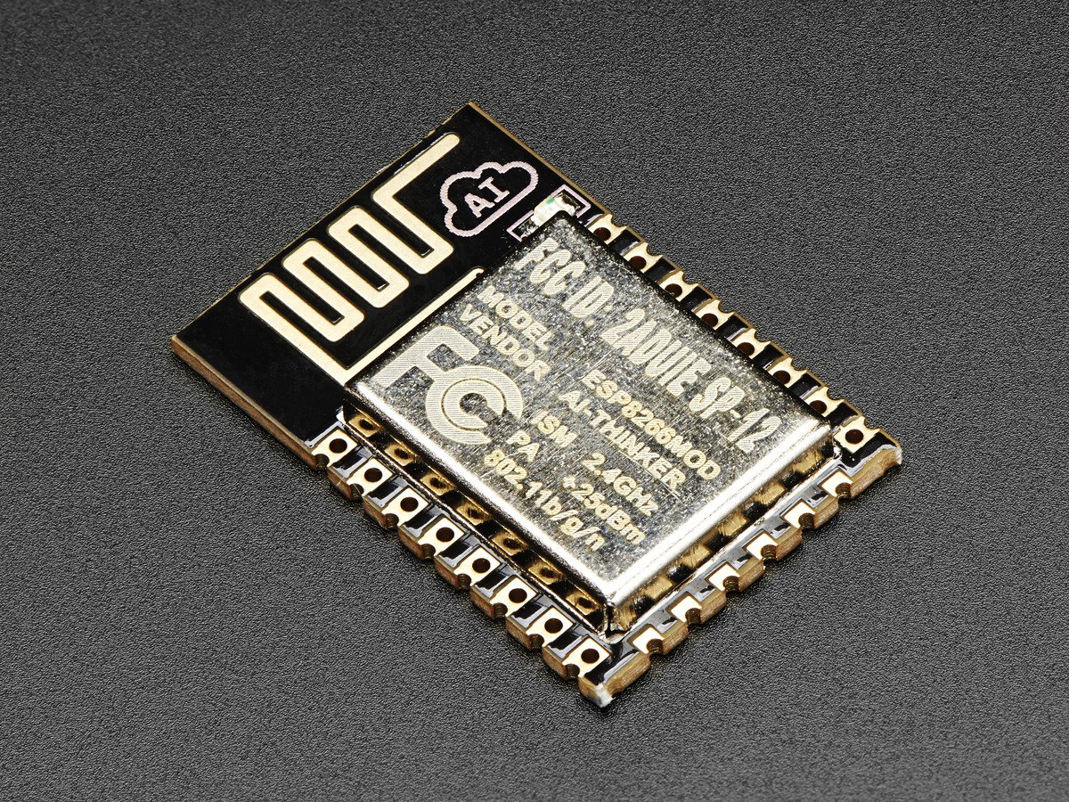
Officially supported SDK
Espressif now has 3 separate SDKs, which are NONOS SDK, RTOS SDK, and Arduino. All 3 have their own perks, suitable for particular purposes and they use similar HAL APIs. At the moment, Arduino are widely used due to its ease-of-use, good software structure and making good use of libraries.
ESP8266 NONOS SDK
NONOS SDK since version 2.0.0 is fairly stable and provides almost all functions that ESP8266 is capable of:
-
APIs for Timer, System, Wifi, reading\writing SPI Flash, Sleep and hardware peripherals: GPIO, SPI, I²C, PWM, I²S với DMA.
-
Smartconfig: Support for fast configuration of Wi-Fi. -
SnifferAPI: Wireless packet capture at 2.4Ghz. -
SNTPAPI: Time syncing with a Time Server. -
WPA2 EnterpriseAPI: Provide a management system for WiFi by using accounts form RADIUS servers. -
TCP/UDPAPI: Allows for Internet connection and supports for protocols such as: HTTP, MQTT, CoAP. -
mDNSAPI: Locating the IP of devices in a network using hostname. -
MESHAPI: Connecting ESP8266 modules in a mesh. -
FOTAAPI: Firmware Over The Air. -
ESP-NowAPI: Using wirelessly transmitted data package at 2.4GHz to communicate directly with other ESP8266s without an Access Point. -
Simple PairAPI: Set up a secured connection between two devices.
ESP8266 RTOS SDK
RTOS SDK has FreeRTOS at its core, and almost all NON OS SDK APIs are compatible with RTOS SDK.
ESP8285
ESP8285 is a successor of ESP8266EX, they are identical except ESP8225 has an 1 MiB internal Flash, rendering SPI FLASH obsolete and in turns reducing size and manufacturing cost.
Module and development board
ESP8266 needs at least 7 extra components for proper functionality, one of which is antenna. The antenna requires top-notch equipments for manufacturing and testing. For that reason, many modules and development boards are pre-built to work out-of-the-box.
Module |
Pins |
Pitch |
LEDs |
Antenna |
Shielded |
Dimensions |
ESP-01 |
6 |
0.1" |
Yes |
PCB |
No |
14.3 × 24.8 |
ESP-02 |
6 |
0.1" |
No |
U-FL |
No |
14.2 × 14.2 |
ESP-03 |
10 |
2mm |
No |
Ceramic |
No |
17.3 × 12.1 |
ESP-04 |
10 |
2mm |
No |
None |
No |
14.7 × 12.1 |
ESP-05 |
3 |
0.1" |
No |
U-FL |
No |
14.2 × 14.2 |
ESP-06 |
11 |
misc |
No |
None |
Yes |
14.2 × 14.7 |
ESP-07 |
14 |
2mm |
Yes |
Ceramic+U-FL |
Yes |
20.0 × 16.0 |
ESP-08 |
10 |
2mm |
No |
None |
Yes |
17.0 × 16.0 |
ESP-09 |
10 |
misc |
No |
None |
No |
10.0 × 10.0 |
ESP-10 |
3 |
2mm |
No |
None |
No |
14.2 × 10.0 |
ESP-11 |
6 |
0.05" |
No |
Ceramic |
No |
17.3 × 12.1 |
ESP-12 |
14 |
2mm |
Yes |
PCB |
Yes |
24.0 × 16.0 |
ESP-12E |
20 |
2mm |
Yes |
PCB |
Yes |
24.0 × 16.0 |
ESP-12F |
20 |
2mm |
Yes |
PCB |
Yes |
24.0 × 16.0 |
ESP-13 |
16 |
1.5mm |
No |
PCB |
Yes |
18.0 x 20.0 |
ESP-14 |
22 |
2mm |
No |
PCB |
Yes |
24.3 x 16.2 |
ESP8266 development board
ESP8266 module includes only ESP8266 chip and other extra components; however, to function properly, we need to program it before putting it into operation. This process is called programming binary firmware (pre-conpiled on the computer) to the ESP8266 Flash. To put ESP8266 in Program mode, GPIO0 needs connecting to logic 0 (0V - GND) while RESETing the chip. Then the chip is ready for programming.
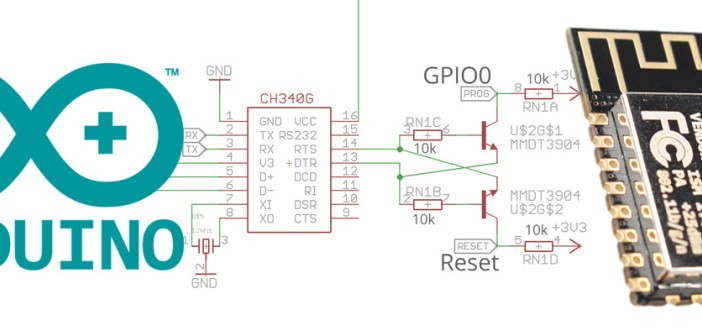
Most development boards have a buil-in programmer, which means they will automatically configure DRT and RTS of USB CDC, put the chip in progamming mode, then download the firmware. Arduino IDE does the same thing, it will tweak all options in accordance with the reported board.
| If you are a beginner and do not know much about hardware, it’d be best to use a development board with built-in programmer. When you start designing the hardware for your project, it’ll then be preferable to use a separate programmer cost-wise. These circuits are easy to find. |
What is Arduino?
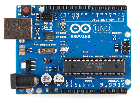
Arduino is an IDE with integrated editor, compiler, and programmer along with firmwares, pre-built libraries for ease of use. The language of use of C/C++. Everything is a collective effort of the community around it. Its philosophy and desgin aim at beginners, amateurs. However, its quality C/C++ compiler and excellent libraries are what make Arduino popular and on the same league with other professional compilers.
One advocate of Arduino was initially AVR, but gradually lots of other vendors like ARM, PIC, STM32 and recently ESP8266, ESP32, RISCV also joined in bringing in more powerful hardware and software capabilities.
Some of Arduino’s features
-
Arduino hides the complication of the hardware layer with simpler concepts, and the complexity of ht software with transparent instructions. Setting up a MCU’s output using registers pose a certain degree of difficulty that even professionals need to look up the datasheet regularly, but Arduino does it with a single function.
-
Thanks to its popularity and easiness and vast libraries, you only need to concern with the final product without knowing much about the protocols, datasheet, etc. These things make it more approachable for newbies and enable them to build amazing things without any prior electronics knownledge.
-
On the other hand, not knowing enough is a drawback, the majority often find it impossible to handle issues outside the scope of the libraries.
-
Prototypes made with Arduino are not durable, their purpose is to cut time-to-market.
Benefits of using Arduino
-
IDE are designed to work well with many compilers and different hardwares without sacrificing for efficiency. For instance: Vanilla Arduino for AVR, but there are other versions for STM32, PIC32, ESP8266, ESP32, etc., optimising existing libraries.
-
Libraries are developed upon top layer APIs, thus these can be reused for all chips. In particular, Arduino for ESP8266 can utilise over 90% of Arduino libraries.
-
Arduino use C/C++ compiler. Did you know that ESP8266 non-os SDK and ESP8266 Arduino both use the same compiler? The end result is almost identical.
-
C/C++ libraries are structured using OOP thus benefit from layering, inheritance, and good management in large projects. MCUs will become more powerful and its applications are huge. Prior management model in C will be tough.
-
Projects for Arduino are always open source, you can use these for reference to your product for improvement and learn from the masters in the process
-
Arduino emphasises multi-platforms, high modularity, which is suitable for complex and highly complex applications. These applications are real life issues. If you are not familiar with C++, or experience problem with overcontrol then give Arduino a try
-
You can save a lot of time by focusing on what is important in these devices. Time is critical, so spend it wisely.
Arduino community around the world
Arduino for ESP8266 & ESP8266 WiFi Uno Board
ESP8266 WiFi Uno Board is a open source project that promotes a development environment for ESP8266 using Arduino. This allows you to write a Sketch with similar libraries and functions to those of Arduino that can run directly on ESP8266 and no additional MCU is required.
ESP8266 Arduino core are bundled with libraries for connecting WiFi that supports TCP, UDP and application protocols such as HTTP, mDNS, SSDP, DNS Servers. In addition, there are libraries for OTA firmware update, Filesystem running from Flash or SD card, servomotors, SPI, I2C peripherals.
Node.js
Node.js® is a JavaScript runtime built on Chrome’s V8 JavaScript engine for Chrome. Node.js allows execution of JavaScript code on server-side, accesses system resources and runs most of OS task using JavaScript and C++ linking.
Lots of companies nowsaday implement Node.js in their production system (e.g Paypal). Node.js-based microservices are also deployed in many leading tech companies.
Cloud platforms of numerous companies support executing Node.js (e.g. Amazon Lambda, Google Script, IBM Blumix, Microsoft Azure)
JavaScript is continuously improved with the latest version Ecmascript 6 (ES5, ES2015) and at an astouding pace. It comes with many benefits such as accessibility, simplicity, OOP, etc.
Another reason for Node.js popularity is that most Web and Mobile developers already know JavaScript, now Node.js enables them to deploy applications on server-side without using another lanugage (historically Java, PHP, etc.)
Why we use Node.js in this book
A full-fledged Internet of Things is undoubtedly complicated: devices, server processing, database, analysis system, data reporting, artificial intelligence. A Google Iot Core diagram
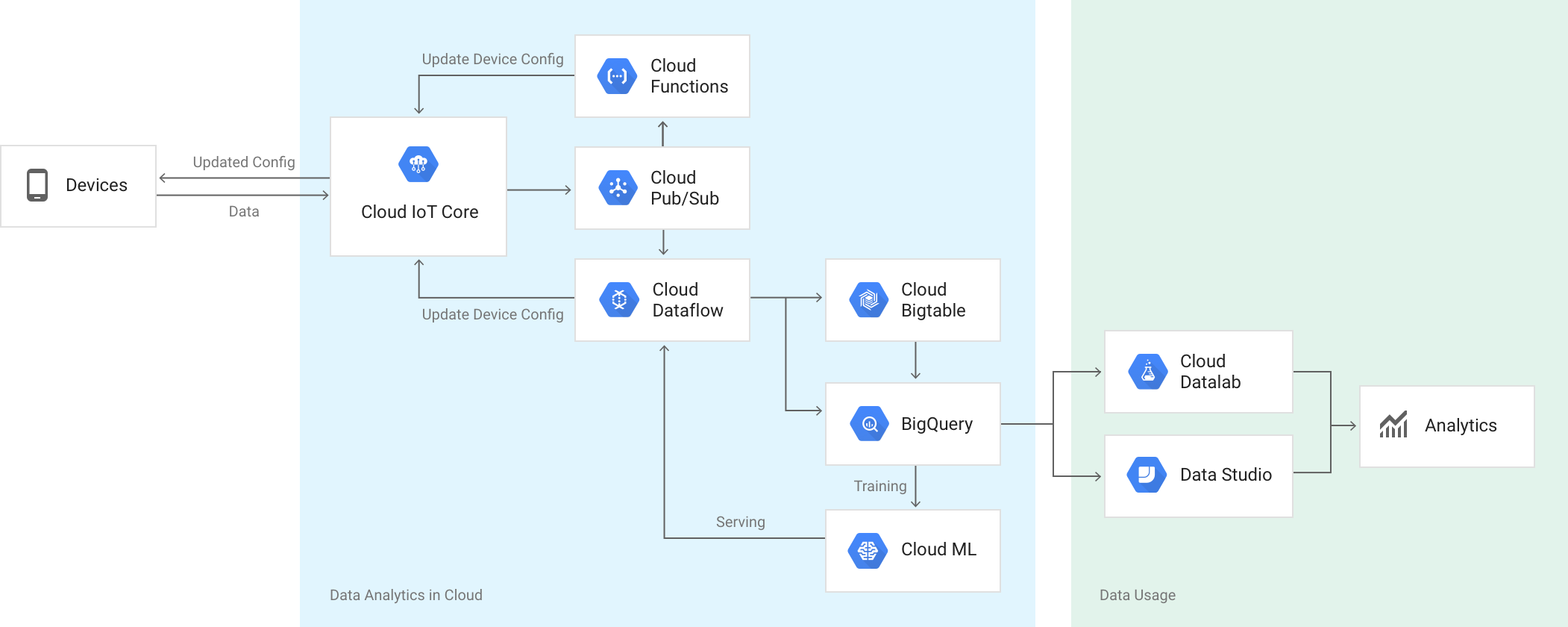
Server is a crucial part in an IoT system. With all its merits, Node.js is exellent for server-side development in IoT. Besides, Node.js is supported by an active community, finding a suitable package is efforless, which in turn saves lots of time.
Does this book teach Node.js ?
Regrettably No, but don’t feel disappointed, Node.js applications in this book are quite simple and not so intensisve, just enough so you can get started with Node.js programming.
Sublime Text
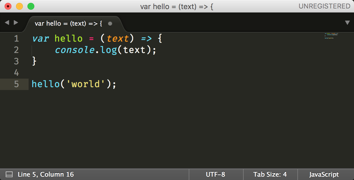
We have Arduino IDE for programming ESP8266, but you still need another text editor for Node.js. Aside from Sublime Text, you might prefer others such as Atom or Visual Code; however, Notepad is not recommended.
Sublime Text is among developers' first choice due to many reasons with speed is a major factor, sometimes considered to be the fastest. Also it’s free (it frequently reminds you of purchase, which many developers find content with)
Installation and Preparation Requirements
Arduino IDE
Step 1: install the Arduino software.
Download and install Arduino IDE from arduino’s homepage. Link donwload: www.arduino.cc/en/Main/Software.
Depending on the operating system, you may choose the appropriate installation package.
Step 2: Install the toolkit, compiler, SDK. That supports the ESP8266 chip in the Arudino IDE.
With this toolkit, we can easily program, compile, and use libraries for the ESP8266 directly on the Arduino IDE. Open Arduino IDE in the menu bar, select File → Preferecens, in settings tab, you need to choose optionsthe options like the image below:
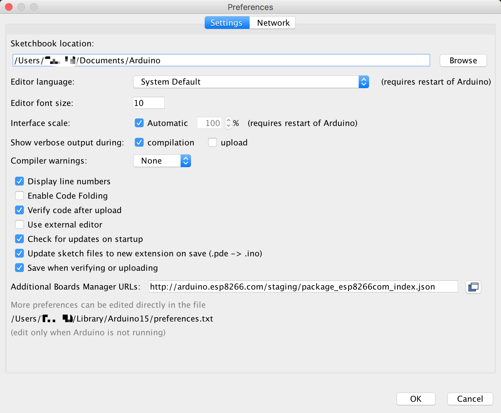
Sketchbook location is the path, which you want to save the sketch (program file), On the Unix-like systems the default path is: /home/name_your_computer/Arduino. This will also be the location of the libraries that we will add later.
In the Additional Board Manager URLs field, enter path http://arduino.esp8266.com/stable/package_esp8266com_index.json.
Step 3: Install ESP8266 board.
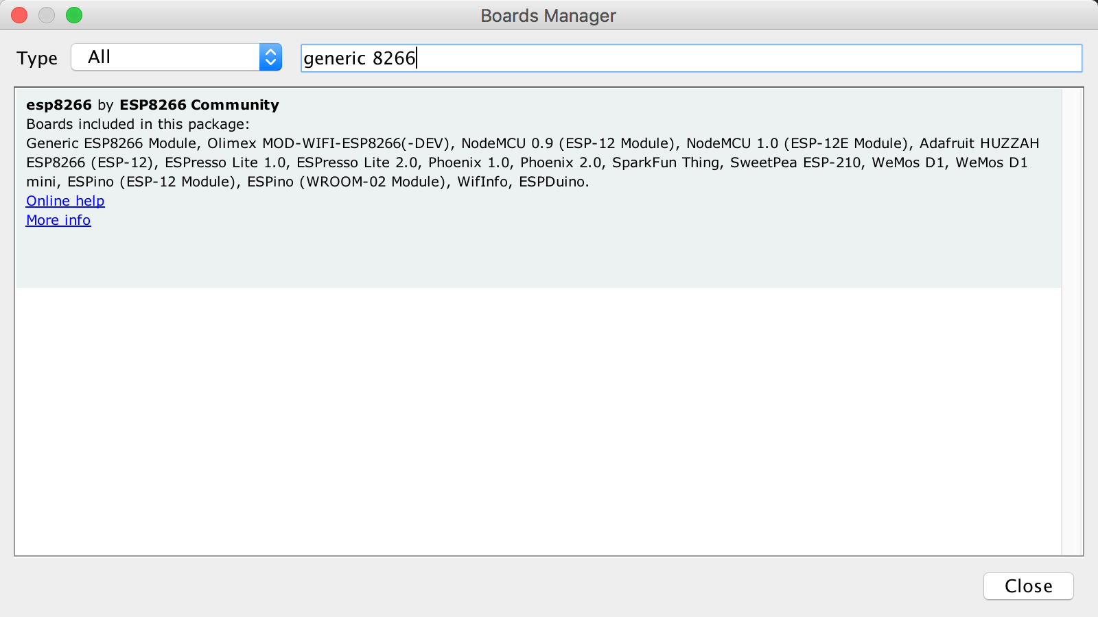
Open Boards Manager in the Tools on menu bar → find the board you want to use with keyword Generic 8266 → select the board ti install as image below and click install.
Install arduino library
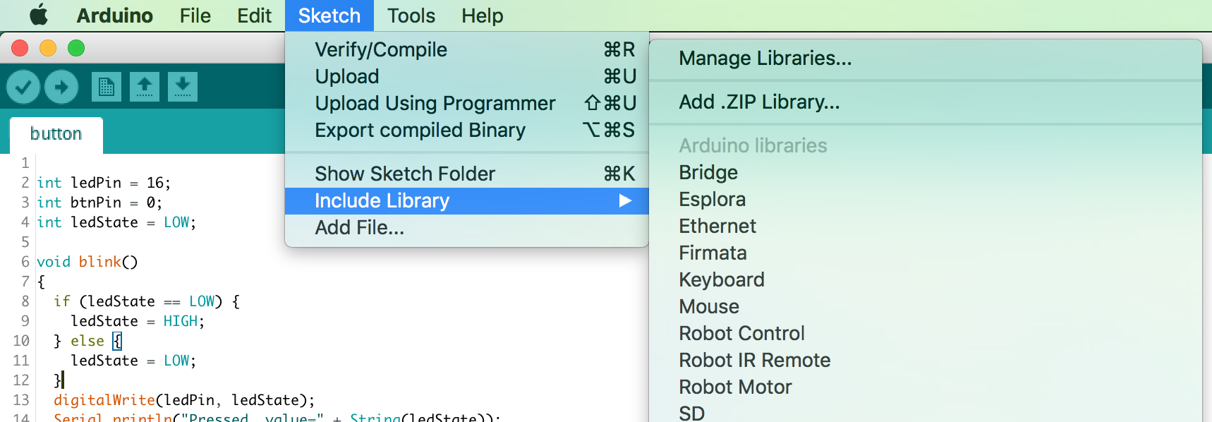
Some libraries published by other developers, you can install it directly using Arduino’s Library Manager.
Start the arduino IDE and select the item Sketch ⇒ include library ⇒ Manage libraries:
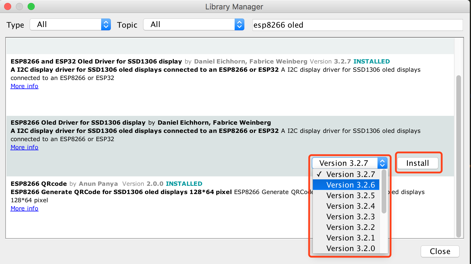
In the libbrary manager , you need to enter the contents of the library in the textbox, select the version, and then press install, the installed libraries will have the text INSTALLED displayed at the top of each library.
For example, we will find the OLED library related to ESP8266 as shown below::
USB CDC driver.
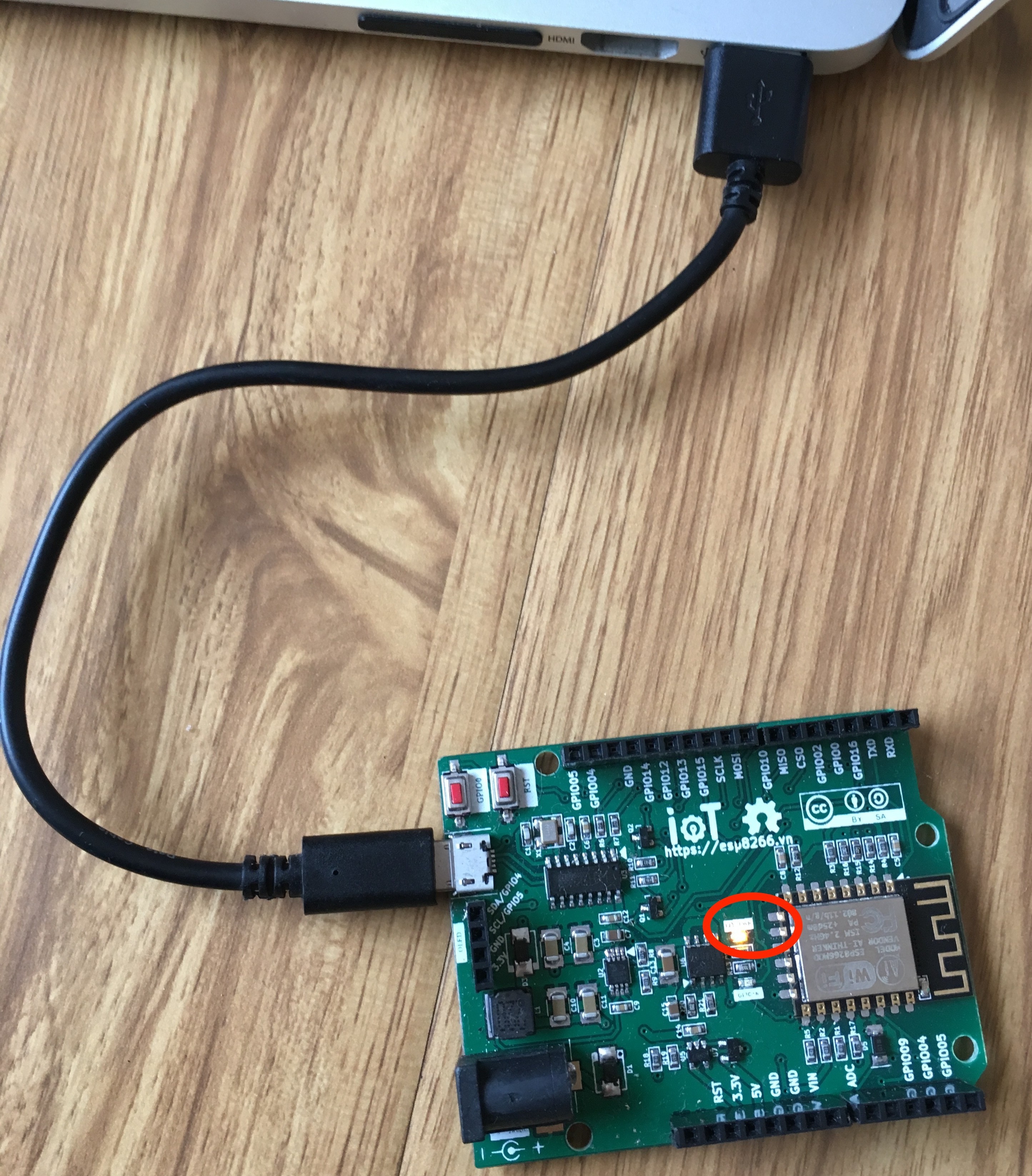
The ESP8266 WiFi Uno board is connected to the computer via a USB MicroB and uses the chip CH340 to convert USB to UART. Therefore, you need to install USB driver software to communicate with the board.
Connect the USB cable to the board, making sure the LEDs in the circle the light as shown below:
Windows & Linux
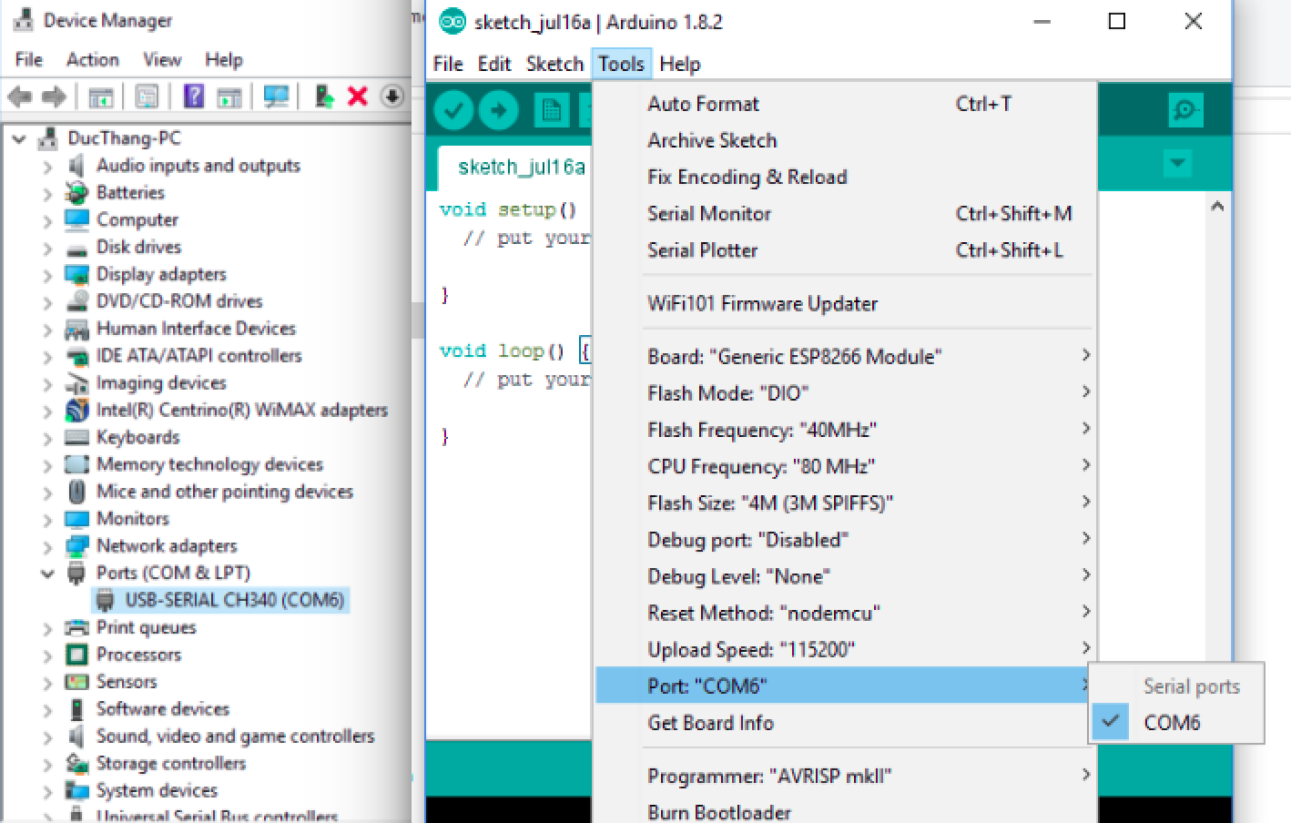
Download the USB driver installation for Windows www.wch.cn/download/CH341SER_ZIP.html and Linux www.wch.cn/download/CH341PAR_LINUX_ZIP.html . Follow the installation requirements. After installation, the result is displayed on the Arduino as image
Mac OS
Download the installation: arduino.esp8266.vn/_static/download/CH34x_Install_V1.3.pkg
For Mac OS Sierra and later versions if you have problems with RESET your machine, you need to handle the following:
-
Open "Terminal"
cmd + space-→ Enter Terminal -
delete driver:
sudo rm -rf /System/Library/Extensions/usb.kext -
With some machines, you have to do extra work
sudo rm -rf /Library/Extensions/usbserial.kext -
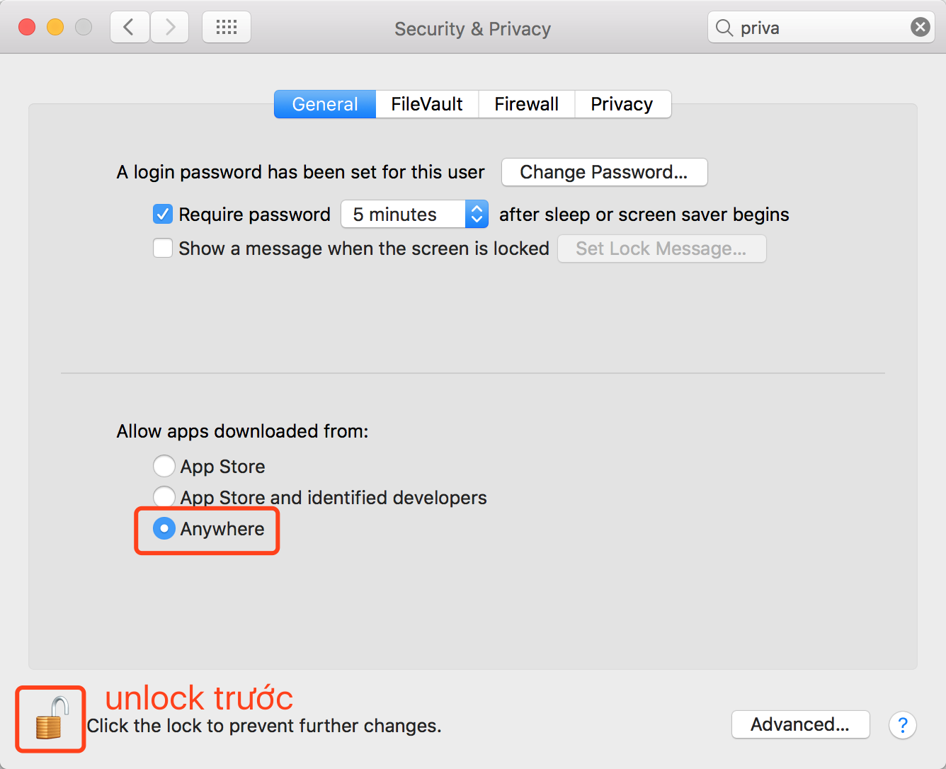
If you can not do the command above, you need to change
Security and PrivacyinSystem Preference. SelectAllow Apps Downloaded FromformMac App Store and Identified DeveloperstoAnywhere- and download CH34x_Install_V1.3.pkg to install again.
Select Board ESP8266 WiFi Uno in Arduino IDE
After the connection and installation are complete, a virtual COM port will appear on your computer. (Depending on the type of operating system that has port names like COM1, COM2 … for Windows, /dev/tty.wchusbserial1420 on Mac OS, /dev/ttyUSB0 on Linux)
Open Arduino IDE and select (refer to connection configuration as image below):
-
Select the configuration for the ESP8266 WiFi Uno Board image::01-intro/port-setup.png[Cấu hình Board ESP8266 WiFi Uno, align="center", width=400]
-
Board:
Generic ESP8266 Module. -
Flash Size:
4M (3M SPIFFS). -
Port: Select the port when the device plugged
-
Upload speed: choose the highest speed, if the computer loaded program is faulty, we will choose the lower speed.
-
Load the program file into the board using the Arduino IDE
On the Arduino interface there are two buttons, the leftmost is the Verify button, for compiling the program, which is equivalent to the Sketch> Verify / Compile function. The next button is Upload, which is equivalent to the function Sketch> Upload. After selecting the appropriate board, the program has no errors, then click Upload to load the program into the board.
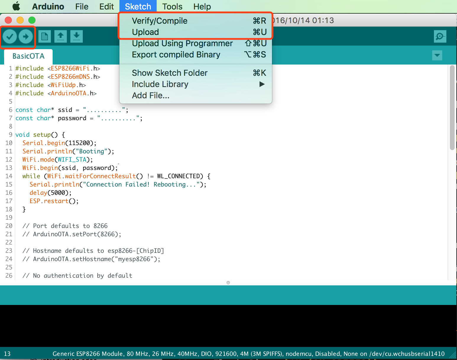
export firmware binary in Arduino IDE
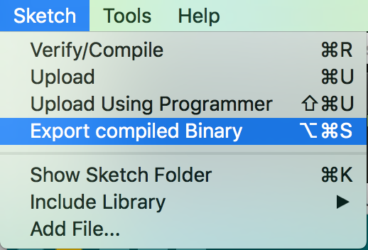
If we need a binary file , we can export the file by Sketch> Export compiled Binary, and the .bin file will be in the Sketch folder.
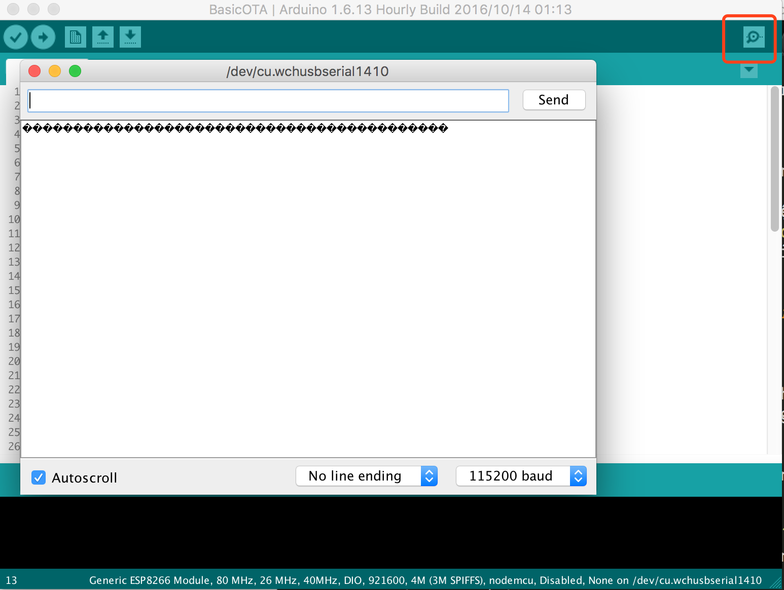
Serial Terminal
There are many free applications to interact with the Serial port on your computer:
-
Windows: PuTTY, realterm
-
Linux: minicom, screen
-
MacOS: minicom, screen
using Arduino IDE Serial Monitor
Arduino has a built-in Serial Monitor, when you select the correct Serial port, you can press the Serial icon on the IDE to open:
Node.js
Download and install Node.js : nodejs.org/en/download/
Sublime Text
Download and install Sublime text : www.sublimetext.com/
Git
This is a support tool that you should also install and use, it does not help you become a programmer, but it helps a programmer become professional and effective git-scm.com/
Summary
At this point, you have a basic understanding of the ecosystem, the tools and procedures working with ESP8266 as well as an IoT system. In addition, you can now start developing an ESP8266-based application. All the selected tools work on multiple platforms such as Mac OS, Windows, or Linux.
Hello World
Hello world helps you with the basics: how to compile, how to upload the program, how to use libraries as well as get a hold of Arduino programming structure.
LED Blinking
Knowledge
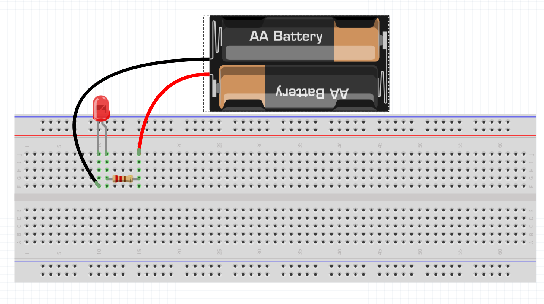
ED = Light Emitting Diodes – a semiconductor that can emit light of different colours depending on its material. To control a LED, a voltage drop higher than Vf (datasheet) is applied between the cathode and anode of the LED, typically 3.2v, and a current lower than its maximum threshold, typically 15mA.

Arduino IDE
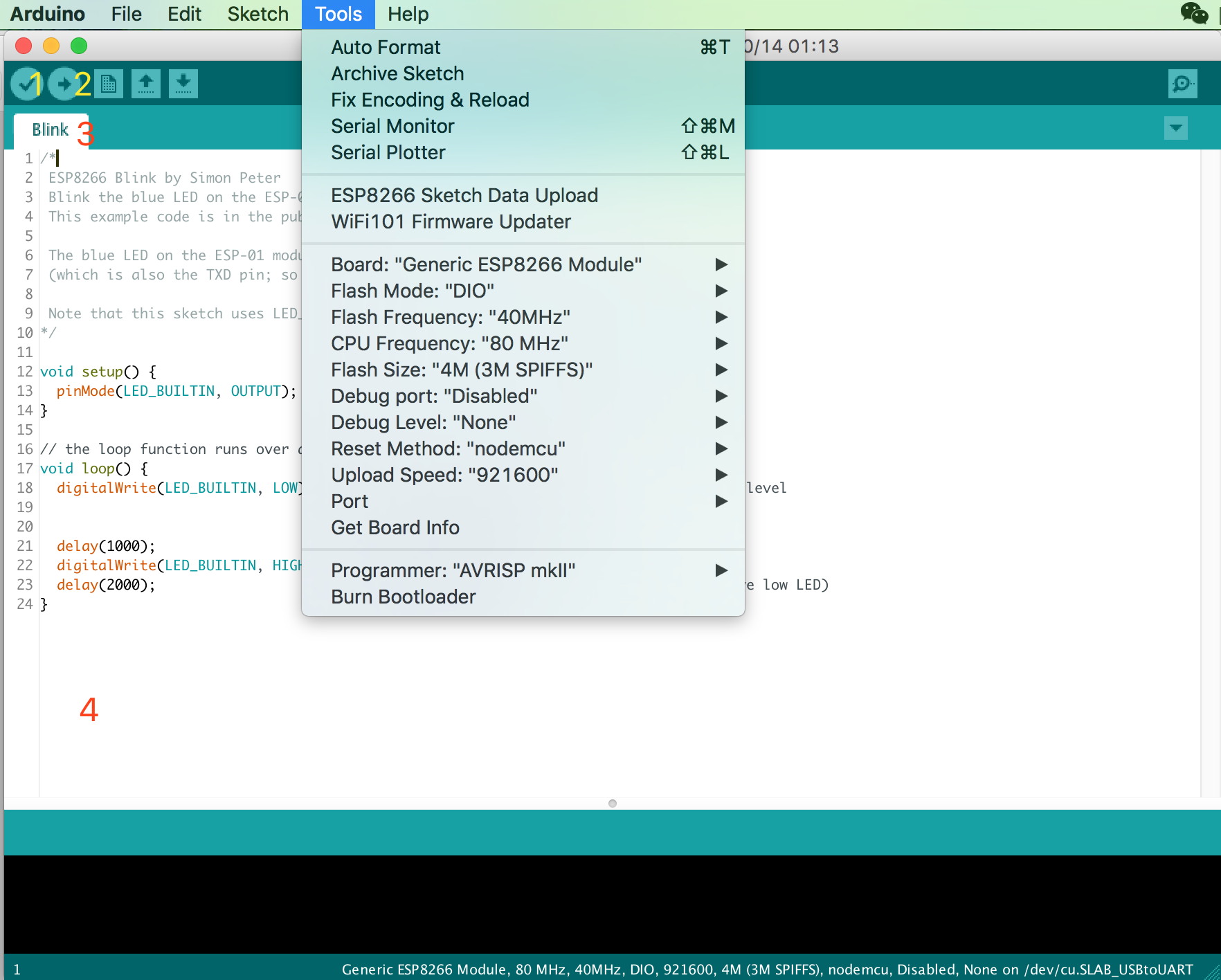
| 1 | Compile the program (check if there is any error). |
| 2 | Compile and upload the program. |
| 3 | File name tab. |
| 4 | ino file content. |
Wiring
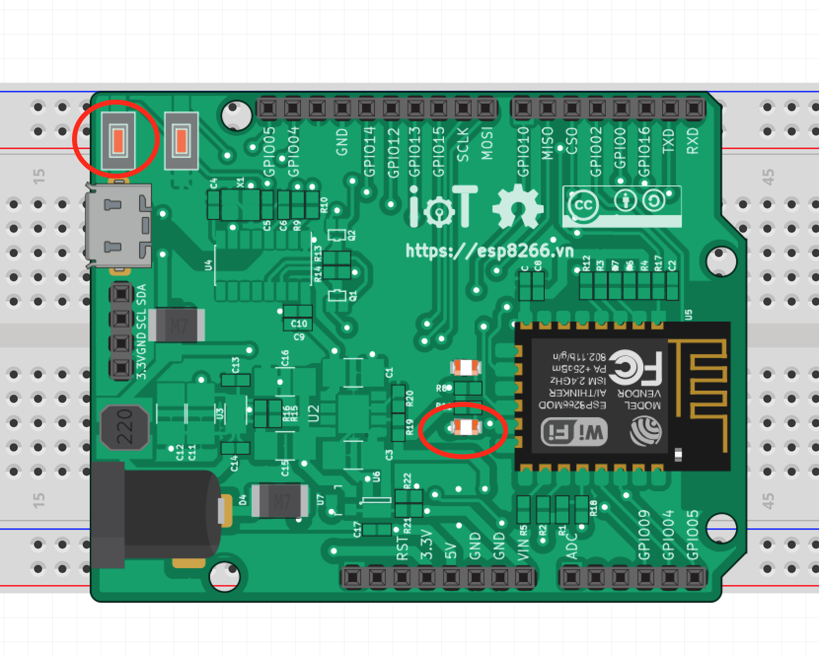
With the source code below, after having checked the program, make sure you Select Board ESP8266 WiFi Uno in Arduino IDE and Load the program file into the board using the Arduino IDE
Source code for blinking using Delay
int pin_led = 16;
/* put your setup code here, to run once */
void setup() {

  pinMode(pin_led, OUTPUT);    // initialize digital pin pin_led as an output
}

/* put your main code here, to run repeatedly */
void loop() {
  digitalWrite(pin_led, HIGH); // LED OFF (HIGH level)
  delay(1000);                 // delay 1s
  digitalWrite(pin_led, LOW);  // bLED ON (LOW level)
  delay(1000);                 // delay 1s
}
Source code for blinking using timer
int ledPin = 16;
int ledState = LOW;
unsigned long previousMillis = 0;
const long interval = 1000;

void setup() {
  pinMode(ledPin, OUTPUT);
}

void loop() {
  unsigned long currentMillis = millis();
  if (currentMillis - previousMillis >= interval) {
    previousMillis = currentMillis;
    if (ledState == LOW)
      ledState = HIGH;  // change status
    else
      ledState = LOW;   // change status
    digitalWrite(ledPin, ledState);
  }
}
Digital IO
Pin name in Arduino (Pin number) is similar to ESP8266’s pin order. pinMode, digitalRead, and digitalWrite use the same Pin Number, for instance to read GPIO2, we call digitalRead(2).
GPIO0 to GPIO15 can either be INPUT, OUTPUT, or INPUT_PULLUP. GPIO16 can either be INPUT, OUTPUT or INPUT_PULLDOWN_16. After hardware reset, all pins are configured as INPUT by default. INPUT.
Each pin serves a particular function; for instance Serial, I2C, SPI. These functions will be configured accordingly using libraries.
GPIO6 and GPIO11 are not present as they are used to program Flash memory. Attempt to use these pins will result in errors.
| Other boards and modules (i.e. ESP-12ED, NodeMCU 1.0) don’t have GPIO9 and GPIO11 since they are used for DIO mode in Flash, while ESP12 uses QIO mode. |
GPIO Interrupt is supported with attachInterrupt, detachInterrupt GPIO Interrupt can be assigned to any GPIO except GPIO16 and it is also compatible with Arduino standard interrupt such as : CHANGE, RISING, FALLING.
Summary
Extended application
-
Fading LED ( on or off gradually)
-
LED blinking using Ticker == Nút nhấn
Knowledge
Buttons help the ESP8266 to activate a process when necessary. In many applications, we often require some sort of external trigger. Throughout this book, we will use buttons to activate some demonstrations as well as LEDs for status indication. In this part, pushing the button will change the LED status (from on → of and vice versa).
This is a simplified demonstration, in reality, processing a button is quite complicated. Mechanical button often produces a chain of pulses (noise, bouncing, etc.). Usually a logic state of a pin should be maintained for 100 milliseconds to be considered stable.
Besides using interrupt for button detection – this method also helps conserve CPU resources, which only occurs when there is an expected event, there is another method called polling: This method requires the CPU to constantly check for the button status. However its responsiveness is inferior to that of interrupt.
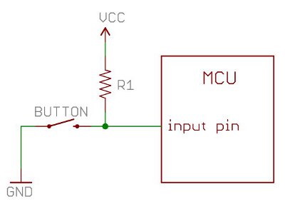
| Requirement: button (GPIO0) for blinking LED (GPIO6) and print out to Serial port. |
| ESP8266 WiFi Uno with pre-built button on GPIO0 |
Proceed after checking the source code:
Source code using polling
int ledPin = 16;                 // LED is connected to pin GPIO16
int btnPin = 0;                  // Push button is connected to pin GPIO0
int ledState = LOW;

void blink()
{
  if (ledState == LOW) {
    ledState = HIGH;
  } else {
    ledState = LOW;
  }
  digitalWrite(ledPin, ledState); // Reverse state of led & and print out serial terminal
  Serial.println("Pressed, value=" + String(ledState));
}

bool isPressed()
{
  return (digitalRead(btnPin) == 0);
}
void setup()
{
  pinMode(ledPin, OUTPUT);       // Sets the digital pin as OUTPUT
  pinMode(btnPin, INPUT_PULLUP); // The push button is configured as a pull-up input

  Serial.begin(115200); // Sets the data rate in bits per second (baud) 115200 for serial data transmission
}

void loop()
{
  if (isPressed()) {
    blink();
  }
}
Source code using interrupt
int ledPin = 16;                 // LED is connected to pin GPIO16
int btnPin = 0;                  // Push button is connected to pin GPIO0
int ledState = LOW;

void blink()
{
  if (ledState == LOW) {
    ledState = HIGH;
  } else {
    ledState = LOW;
  }
  digitalWrite(ledPin, ledState);
  Serial.println("Pressed, value=" + String(ledState));
}
void setup()
{
  pinMode(ledPin, OUTPUT);      // Sets the digital pin as OUTPUT
  pinMode(btnPin, INPUT_PULLUP); // The push button is configured as a pull-up input
  attachInterrupt(btnPin, blink, FALLING); //set interrupt in btnPin
  Serial.begin(115200); // Sets the data rate in bits per second (baud) 115200 for serial data transmission
}

void loop()
{
  //do nothing
}
Some concepts
-
Interrupt Interrupt is a hardware-related concept; an arbitrary event occurs, which requires the CPU to halt all on-going tasks to server the Interrupt routine. For instance, an interrupt is activated when there is a change from logic 1 to 0 (falling edge) of a GPIO, when the change occurs on that GPIO, CPU will immediately halt, save the main program’s context and jump to the Interrupt service routine to execute the instructions.
-
pull-up/pull-down Most GPIO pins have 3 states, one is output high (logic 1), another one is output low (logic 0) and the last one is input. In input state, a GPIO assumes high impedance (Hi-Z) state or isolated state, no current can pass through although the pin can still sense voltage level. In this Hi-Z state, if no initial logic is defined, the GPIO will float, which means it is susceptible to external factors; when read it will not have a consistent logic state. Pull-up means pulling a resistor connected to a GPIO to logic 1, defining an initial logic level of 1 to ensure it remains that way unless externally modified. Similarly, pull-down defines GPIO’s initial logic level of 0.
OLED
OLED display
OLED display (Organic Light Emitting Diode) is a type of display composed of a film of organic compound situated between cathode and anode. It emits light in respond to an electric current. As it uses organic semiconductor, backlight is redundant, which is more effective than traditional LCD in terms of size and cost. Outdoor performance is decent compared to LCD.
SSD1306 OLED display
A small display ranging from 0.96 in to 1.25 in that is commonly seen in electronics. The driver MCU is SSD1306. This chip interfaces with external MCUs using I2C
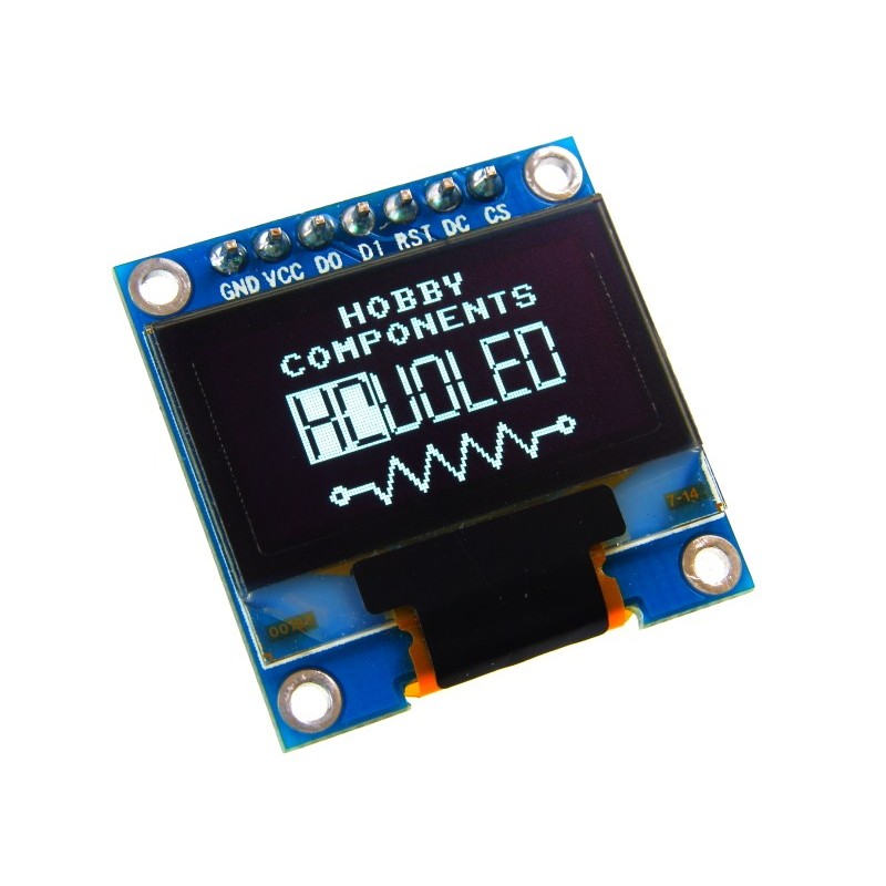
I2C interface
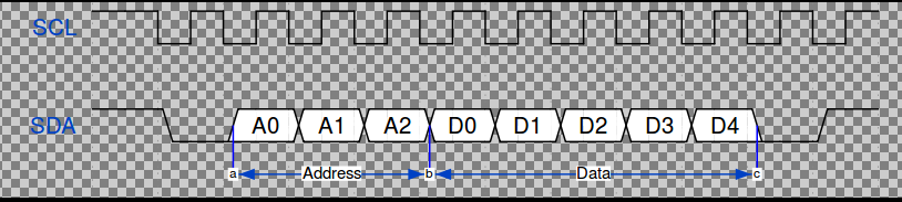
I2C (Inter-Integrated Circuit) is a serial interface developed by Philips for transmitting data between IC. I2C uses 2 transmission lines, one is serial clock (SCL) generated by a Master and another one is full-duplex serial data (SDA)
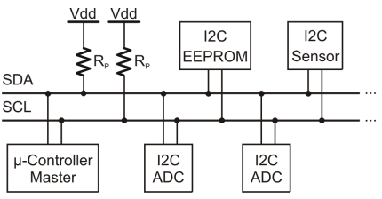
are required as shown in the figure. The nominal value is usually 4k7 or 1k2, depending on the speed and distance
OLED Display with ESP8266
Step 1: Wiring Connect GPIO4 of ESP8266 with SDA of OLED, and GPIO5 with SCL. Connect 3v3 with VCC and the GND for OLED. However, ESP8266 IoT Uno has default pin header for OLED, which is illustrated in the figure
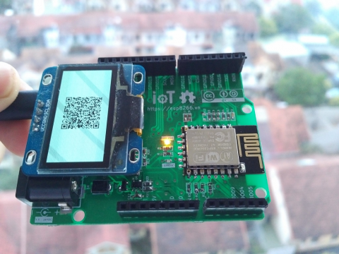
Step 2: Installing library ESP8266 and ESP32 OLED driver for SSD1306 display, see more Install arduino library
Step 3: Programing We will demonstrate a digital clock on OLED Display
#include <Wire.h>
#include "SSD1306.h"

SSD1306  display(0x3c, 4, 5);
int thoi_gian = 0;
void setup()
{
  Serial.begin(115200);
  display.init();
  //display.flipScreenVertically(); //đảo chiều
  display.setFont(ArialMT_Plain_10);
  display.drawString(0, 0, "Hello world");
  display.display();
  delay(1000);
  display.clear();
}

void loop()
{
  int gio, phut, giay;


  delay(1000);
  thoi_gian ++;

  gio = thoi_gian/3600;
  phut = (thoi_gian%3600)/60;
  giay = thoi_gian % 60;
  display.clear();
  display.drawString(0, 0, String(gio) + ":" + String(phut) + ":" + String(giay));
  display.display();
}
Proceed after checking the source code:
Summary
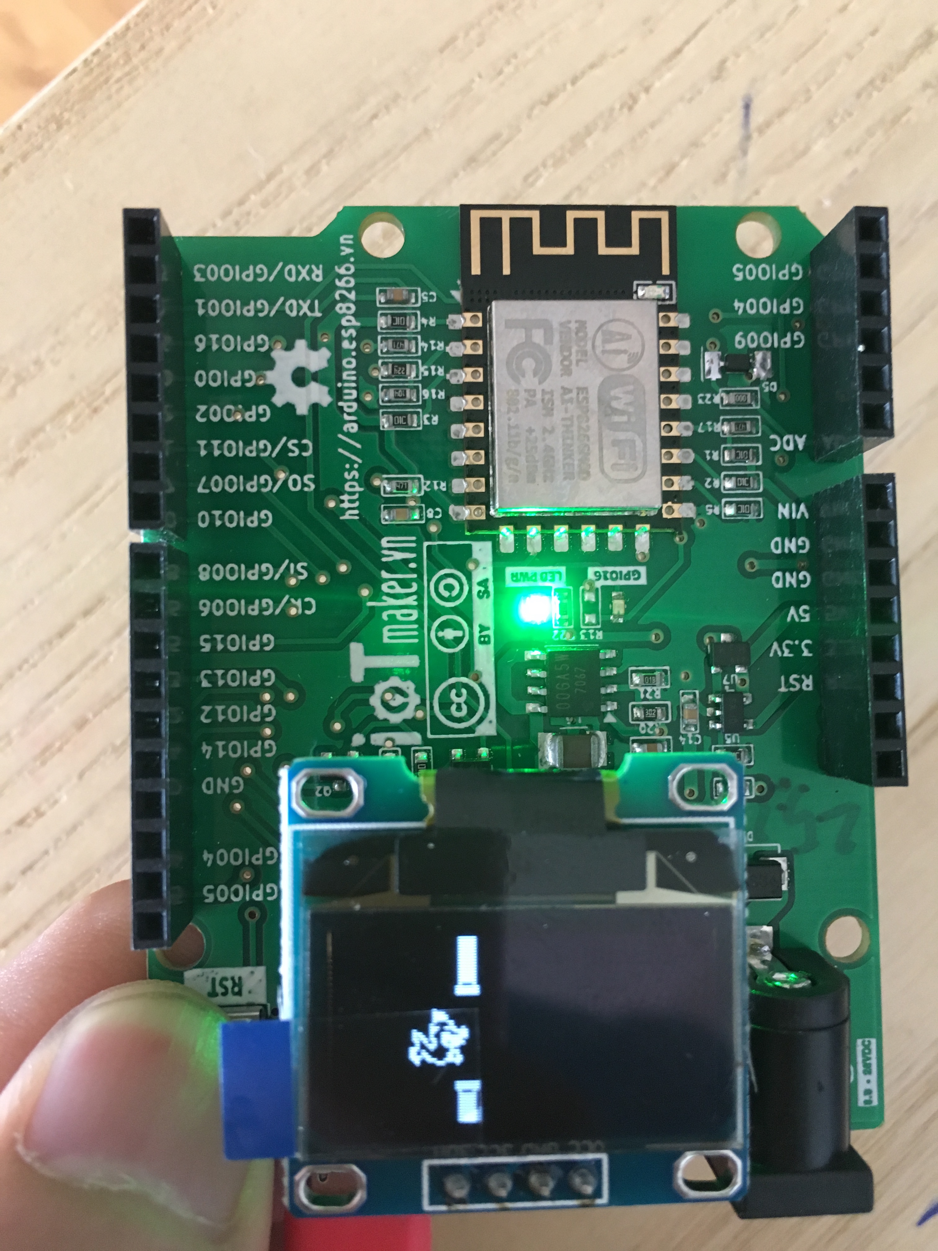
Through some examples with LEDs, buttons and OLED, we can extend to other uses of GPIO in ESP8266, and gain some in-depth understanding on how Arduino IDE works, how to upload and use libraries, etc. One application that makes use of said knowledge is Flappy Bird. You can try it out here: https://github.com/esp8266vn/arduino-flappybird
ESP8266 WiFi
WiFi connection is ESP8266’s selling point, it can connect to existing Router at home and Access Point with the most current standard in the 2.4Ghz frequency range - in STA mode. In addition, ESP8266 also supports AP mode (Access Point), i.e. it will initiate an Access Point and allow clients to connect, or it can run in mode STA and AP mode.
STA mode is frequently used in many applications, it will connect to a local WiFi with Internet enabled and send data to a server. Other occasions see it operating in AP mode, which is is programmed to exchange data between ESP8266 and a computer (or other device with a browser), e.g. controlling a LED using ESP8266 as a Web Server
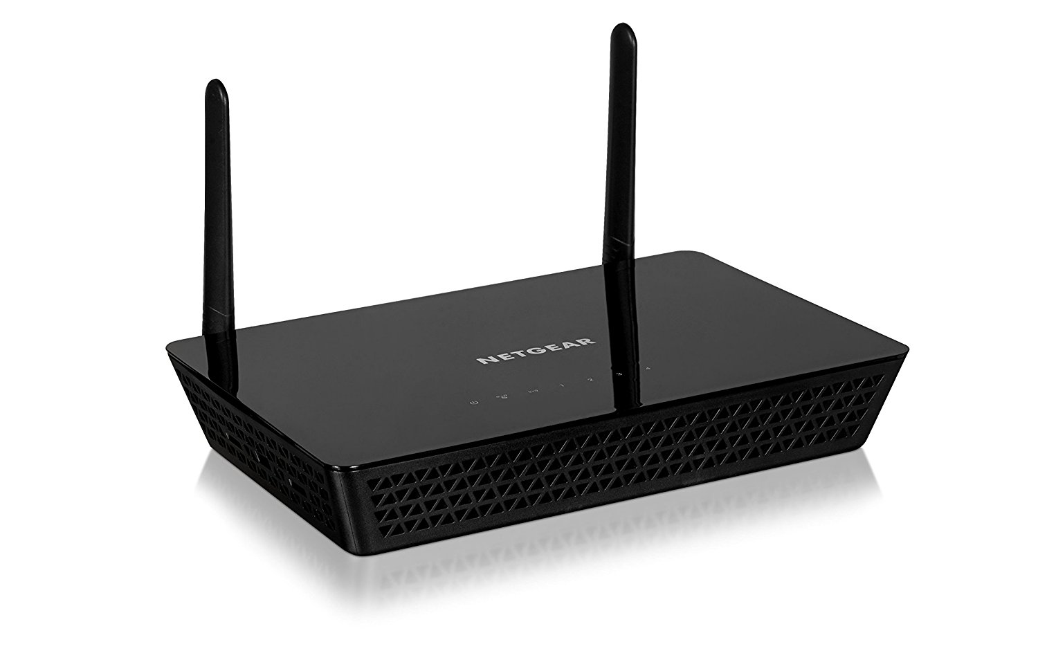
WiFi Access Point is a central networking device in charge of directing data streams, e.g. process IP packets to identify LAN address, forwarding packets from the Internet to the stations.
A deviced connecting to an Access Point is called a Station. Any laptop or desktop with WiFi card connecting to an Access Point is identified as a Station.
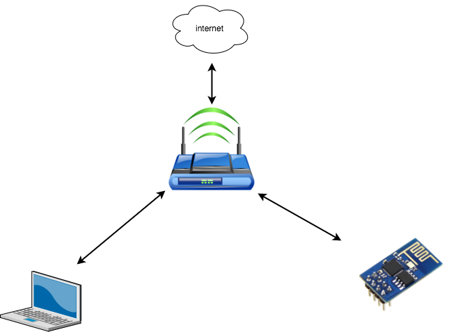
All Stations when attempting to connect to a Access Point need to identify a desired BSSID, it is commonly called SSID when refering to a WiFi network. A list of nearby SSIDs can be scanned on a computer when using WiFi.
The following modes will be coverd in this chapter
-
Station - STAmode connects to a existing Access Point. -
Using
HTTPClientto request and receive data from the Internet. -
Access Point - APmode allows connections from other clients. -
Web Serverrunning on ESP8266 for toggling LEDs.
WiFi Station Mode
Knownledge
To connect to the Internet, ESP8266 needs to connect to a local WiFi network, and this network must connect to a Internet WAN. Most modems nowsaday have WiFi Access Point intergrated, which make it easy to deploy IoT application.
ESP8266 must be in Station (STA) mode to connect to a local WiFi network, and must be supplied with a SSID and a password.
Each Access Point implements a security protocol in connections with Stations, e.g. WEP, WPA2. Howver, this would not be an issue in development since ESP8266 has pre-configured the necessary protocol.
Upon successful connection to a network, ESP8266 automatically initialise a default DHCP Client, requesting for IP before accepting any IP connection. Thus, for some reason if a DHCP Server is not available, static IP must be manually configured for ESP8266.
Connecting to a local network
With the provied code, if a given SSID and PASSWORD are correct and an Access Point is up and running, the module will establish a connection and print out the Serial Terminal the provided local IP of ESP866 in the LAN network.
#include <ESP8266WiFi.h>

const char* ssid     = "your-ssid";
const char* password = "your-password";

void setup() {

  // Initiate a serial connection at 115200 bits/s
  Serial.begin(115200);
  delay(10);
  Serial.print("Connecting to ");

  // Print out the name fo the WiFi (SSID)
  Serial.println(ssid);

 // Configure the ESP8266 in station mode and connect to a pre-defined WiFi network
  WiFi.begin(ssid, password);
  // Print out . when ESP8266 trying to connect to the network
  while (WiFi.status() != WL_CONNECTED) {
    delay(500);
    Serial.print(".");
  }
  // Print out "WiFi connected" and IP of ESP8266
  Serial.println("");
  Serial.println("WiFi connected");
  Serial.println("IP address: ");
  Serial.println(WiFi.localIP());
}

void loop() {

}
Using WiFiMulti
Nevertheless, as a precaution, having 2-3 WiFi network as backup is advisable, WiFiMulti class will prove useful. A simple monitoring function will notify other functions when a connection is made.
#include <ESP8266WiFi.h>
#include <ESP8266WiFiMulti.h>
// Declare wifiMulti variable of class ESP8266WiFiMulti to use functions of this class.
ESP8266WiFiMulti wifiMulti;
// connectioWasAlive variable to check for ESP8266 wifi connection.
boolean connectioWasAlive = true;

void setup()
{
  Serial.begin(115200);
  Serial.println();
  // Add the pre-defined networks for ESP8266
  wifiMulti.addAP("primary-network-name", "pass-to-primary-network");
  wifiMulti.addAP("secondary-network-name", "pass-to-secondary-network");
  wifiMulti.addAP("tertiary-network-name", "pass-to-tertiary-network");
}

void monitorWiFi()
{
  // Check if there is no WiFi connection then set connectioWasAlive = false
  // while print out "." every 500ms when there is no connection.
  if (wifiMulti.run() != WL_CONNECTED)
  {
    if (connectioWasAlive == true)
    {
      connectioWasAlive = false;
      Serial.print("Looking for WiFi ");
    }
    Serial.print(".");
    delay(500);
  }
   // If a connection is established then set connectioWasAlive = true
  // so when the connection is terminated the program will jump into if (connectioWasAlive == true),
  // annoucing the WiFi scanning process
  else if (connectioWasAlive == false)
  {
    connectioWasAlive = true;
    Serial.printf(" connected to %s\n", WiFi.SSID().c_str());
  }
}

void loop()
{
  monitorWiFi();
}
Proceed after checking the source code:
HTTP Client
HTTP Protocol
HTTP - Hypertext Transfer Protocol, is a protocol for transmitting data among computers in the www (World Wide Web), the data can be text, file, image, or video.
HTTP is designed for data exchange between a client and a server using TCP/IP, the working principle is request/respond, and stateless. A web browser is a client, any machine that hosts web stie is a server. A client connects to a server, sends data composed which includes headers to it. The server receives it and responds based on what it gets, the channel is terminated after each connection.
For instance, when a URL is put in the address bar and Enter is pressed, the Web Client will immediately send the request to the Web Server with the provided address. The Web Server will then send back the content of the web page.
In HTTP protocol, connection is only made from the client side (or HTTP Client). When the client sends the request along with the URL and the payload (what to get) to the server. Server (HTTP Server) listens for any request from the client and responds accordingly. After that, the connection is terminated.
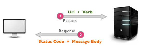
When talking about HTTP, Hyperlink, or URL (Uniform Resource Locator), is a common concept.
URL defines a website’s address and contains the request details from the client, which the server uses to process. Its structure is as follows:
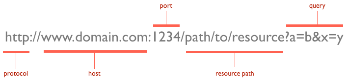
For instance, sending a sensor data to a server can be done via: http://esp8266.vn/log.php?nhiet_do=30
|scheme  | host      |port |path            |query                |fragment|
http:// server.com: 8080 /path/to/log.php ?nhiet_do=30&do_am=80 #test| 1 | scheme defines the protocol to communicate with the server, if it is https then it will be encrypted. |
| 2 | host is the server’s address. |
| 3 | port is where the service is provided, if not defined then port 80 will be used. |
| 4 | path information the client wants to get. |
| 5 | query information the client wants to send. |
| 6 | fragment this attribute directs the browser to a specific location. |
With the above URL put into the address bar, the browser will initiate a connection and send the following information.
GET /log.php?nhiet_do=30 HTTP/1.1
Host: esp8266.vn
User-Agent: curl/7.49.1
Accept: */*
Received information:
HTTP/1.1 200 OK
Content-Type: text/html; charset=utf-8
Transfer-Encoding: chunked
Connection: keep-alive

data
On linux, curl can be used to digest raw data, type curl -v http://esp8266.vn/log.php?nhiet_do=30 in the terminal.
|
HTTP defines some methods for communicating with Server:
-
GETis the most common and widely used method of HTTP. GET retrieves whatever information (in the form of an entity) is identified by the URL, usually the Server returns the data based on the query information it receives without modifying it.pathandqueryin the URL contains query information. -
POSTSimilar toGET, butPOSTcan send data to the Server. -
PUTis a method for creating new resources, similar toPOSTbut it informs the server that if the resource does not exist, the server should create new resource or otherwise modify it. -
DELETESimilar toGET, but requests that the origin server deletes the resource identified by the URL.
Commonly used methods are GET`and `POST; other methods are utilised in API server (RESTful). Differences between POST and GET.
-
GETcan be cached (saved by the browser for future use), the requested content is stored in the history and can be bookmarked. -
GETshould not be used to send sensitive information. -
GETis restricted in terms of data length. -
GETshould only be used to query for data. -
POSTis not cached, not saved in browser history, and cannot be bookmarked. -
POSTdoes not limit the payload amount.
HTTP Header & Status Code
The response always include a header with the first line containing the Status Code HTTP/1.1 200 OK, i.e. status code = 200, the response is valid.
It is then followed by header pairs with information that the Server wants to exchange with the Client, which is hidden from the users. These header pairs are defined as name: value and are terminated with invisible control characters (0x0D 0x0A or \r\n).
In the above example, the header Content-Type: text/html; charset=utf-8 informs the browser the return content is text, utf-8 encoding. Transfer-Encoding: chunked unknown data length, which is send until the server closes the connection.
Some common HTTP status code:
-
1xx: Informational responses. An informational response indicates that the request was received and understood. These status code is defined in HTTP/1.1, which is not available in HTTP/1.0 or previous versions. These status code can be ignored. Common status codes:
-
100 Continue: Informs the client that it can continue by sending the remainder of the request or, if the request has already been completed, ignore this response. In a POST request, the server will reject it if the body is too large. To resolve this, the client must send Expect: 100-continue after the initial header.
-
-
2xx: Success. This class of status codes indicates the action requested by the client was received, understood, accepted, and processed successfully. Common status codes:
-
200 OK: The request has succeeded. This can be seen in these methods GET, HEAD, POST, TRACE .
-
201 Created: The request has been fulfilled, resulting in the creation of a new resource. This is used to verify PUT or POST success.
-
204 No Content: The server successfully processed the request and is not returning any content.
-
-
3xx: This class of status code indicates the client must take additional action to complete the request. Common status codes:
-
301 Moved Permanently: The requested resource has been assigned a new permanent URI and any future references to this resource should use one of the returned URIs.
-
-
4xx: These are intended for situations in which the error seems to have been caused by the client. The server assumes that the Client is experiencing errors with a request or an invalid resource. Common status codes:
-
400 Bad Request: The request could not be understood by the server due to malformed syntax.
-
401 Unauthorized:The request requires user authentication. The client can re-send the request a validated header. If the header includes the authentication but is still refused then the authentication data is wrong.
-
403 Forbidden: The server understood the request, but is refusing to fulfill it.
-
404 Not Found: The resource is invalid or cannot be found on the server.
-
409 Conflict: The Server cannot complete the response because the Client intentionally modify a resource that is different to timestamp của Client. Conflicts are most likely to occur in response to a PUT request.
-
-
5xx: These code indicate cases in which the server is aware that it has erred or is incapable of performing the request. Common status codes:
-
500 Internal Server Eror: The server encountered an unexpected condition which prevented it from fulfilling the request.
-
501 Not Implemented: The server does not recognize the request method and is not capable of supporting it for any resource.
-
503 Service Unavailable: Occurs when the server is under maintenance or overloaded.
-
JSON
is a lightweight data-interchange format. It is easy for humans to read and write. It is easy for machines to parse and generate. It is based on a subset of the JavaScript Programming Language. JSON is a text format that is completely language independent but uses conventions that are familiar to programmers of the C-family of languages, including C, C++, C#, Java, JavaScript, Perl, Python, and many others. These properties make JSON an ideal data-interchange language.
JSON is built on two structures:
-
A collection of name/value pairs. In various languages, this is realized as an object, record, struct, dictionary, hash table, keyed list, or associative array.
-
An ordered list of values. In most languages, this is realized as an array, vector, list, or sequence.
Syntax
-
An object is an unordered set of name/value pairs.
-
Values are separated by ,
, -
An object (name/value) starts and ends with
" -
All objects reside inside a pair of
{} -
JSON data is grouped into pairs of name/value. Each name/value composes of a
namefield ( lies inside a", followed by a:, thenvalue`field comes next (also lies inside a `". For instance:"name":"John"
{
    "username" : "your-user-name",
    "email" : "your-email@email.com",
    "website" : "iota.edu.vn",
    "title" : "IoT Stater Cource"
}
Bitcoin value monitoring application
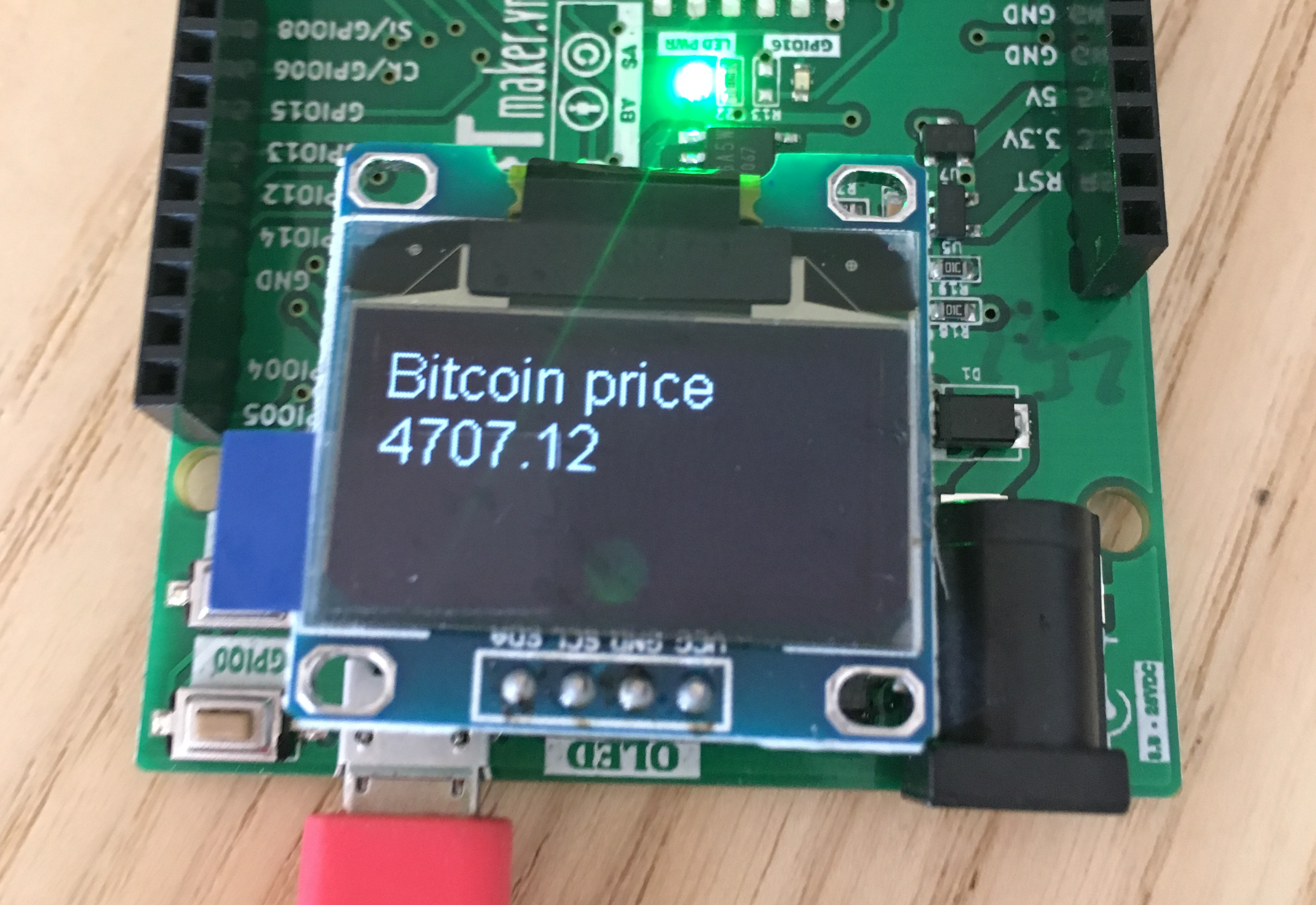
A simple application using HTTP to get Bitcoin (BTC)/USD rate form exchange market web, then display on the OLED.
There are many sites to choose from, for instance www.cryptocompare.com/. With the provided information, and the objective is to get the exhcnage rate of Bitcoin/USD, ESP8266 will send a HTTP Request to min-api.cryptocompare.com/data/price?fsym=BTC&tsyms=USD and get back a JSON packet as follows:
{"USD":4731.44}The USD field is the desired data.
Most websites now offer HTTP encryption, basically it’s still HTTP, but the transmission process is encrypted, and verification is done before the request is sent.
|
When using HTTPS, SHA1 Fingerprint must be provied so that the Client can verify the Server. A browser can be use to access it in advance. In Chrome, after connecting to min-api.cryptocompare.com/data/price?fsym=BTC&tsyms=USD, press Ctrl+Shift+I (Shift + ⌘ + I in MacOS), proceed to Security > View Certificate > Details > Thumbprint. The result will be as follows.
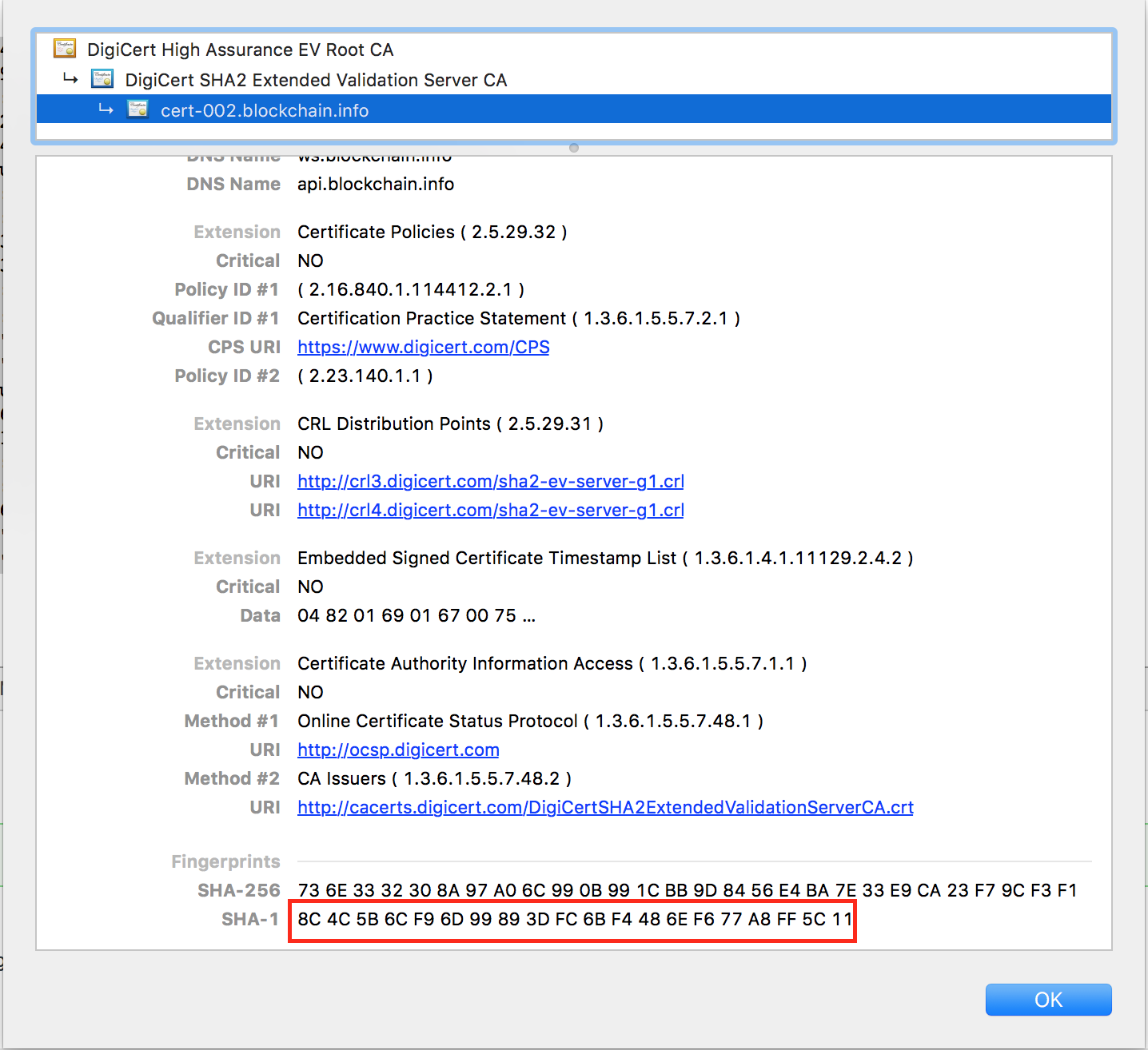
A source code to check for Bitcion price that repeats every 5 seconds, ESP8266 will establish a connection with Cryptocompare server to get the information and print out to the OLED display.
#include <ESP8266WiFi.h>
#include <ESP8266HTTPClient.h>
#include <ArduinoJson.h> //https://github.com/bblanchon/ArduinoJson
#include "SSD1306.h" //https://github.com/squix78/esp8266-oled-ssd1306

const char* ssid = ".....";
const char* password = "....";
SSD1306  display(0x3c, 4, 5);
/* xem thêm https://www.cryptocompare.com/api/ */
const char* host = "https://min-api.cryptocompare.com/data/price?fsym=BTC&tsyms=USD";
/*SHA1 fingerprint*/
const char* fingerprint = "61 DE E9 FF BB 6B AD AA E4 9A 38 95 DC EC 74 2C 61 4B 7D 07";

void getBitcoin()
{
  HTTPClient http;
  Serial.print("connecting to ");
  Serial.println(host);

  http.begin(host, fingerprint);
  int httpCode = http.GET();
  if (httpCode == HTTP_CODE_OK) {
    String payload = http.getString();
    Serial.println(payload);
    StaticJsonBuffer<512> jsonBuffer;
    JsonObject& root = jsonBuffer.parseObject(payload);
    if (!root.success()) {
      Serial.println("parseObject() failed");
      return;
    }

    double priceUSD = root["USD"];
    display.clear();
    display.drawString(0, 0, "Bitcoin price");
    display.drawString(0, 18, String(priceUSD));
    display.display();
    Serial.println(priceUSD);
  }
  http.end();
}

void setup() {
  Serial.begin(115200);
  display.init();
  display.clear();
  display.setFont(ArialMT_Plain_16);
  display.drawString(0, 0, "Connecting to");
  display.drawString(0, 18, ssid);
  display.display();
  WiFi.begin(ssid, password);
  while (WiFi.status() != WL_CONNECTED) {
    delay(500);
    Serial.print(".");
  }
  display.clear();
  display.drawString(0, 0, "Connected");
  display.display();
}

void loop() {
  if (WiFi.status() == WL_CONNECTED) {
    getBitcoin();
  }
  delay(5000);
}
Proceed after checking the source code:
WiFi Access Point Mode
ESP8266 in Access Point Mode
ESP8266 allows other devices (Station - STA) to connect when operating as an Access Point. It can initiate a local WiFi network with DHCP Client enabled to assign IP to connected Clients. Due to RAM constraints, maximum number of STA concurrent connections is 5.
Initiate a network
<ESP8266WiFi.h> is needed, this library contains softAP which is used to configure soft Access Point (soft AP) for a WiFi network.
A simple WiFi network only needs to provide SSID without password WiFi.softAP(ssid). If a password is desired, WiFi.softAP(ssid, password) can be called. More options are available using WiFi.softAP(ssid, password, channel, hidden), default channel is 1 and initially hidden, which can be made invisible by setting hidden = true
ssid should not exceed 63 characters, and the (optional) password is at least 8 characters long for WPA2-PSK
softAP will return true if the WiFi network is successfully established
Remember that the WiFi network created by calling softAP will have a default IP of 192.168.4.1 and run a DHCP Server to provide connected clients with IP in the 192.168.1.x range. The default IP can be modified by calling softAPConfig. Moreover, ESP8266 can operate in both Station and Access Point modes. Take note that the two modes operate on the same channel, softAP channel will be utilised by Station mode.
|
WiFi.softAPConfig (local_ip, gateway, subnet) is used to modify Access Point IP.
192.168.4.22IPAddress local_IP(192,168,4,22);
IPAddress gateway(192,168,4,9);
IPAddress subnet(255,255,255,0);
WiFi.softAPConfig(local_IP, gateway, subnet)WiFi.softAPgetStationNum() returns the number of clients connecting to the Access Point
Establish WiFi network using ESP8266
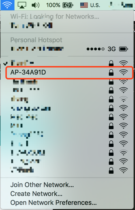
With the following code, a local WiFI network with a SSID of AP-XXXXXX is established and available for connection for computers using the password password
#include <ESP8266WiFi.h>

const char *password = "password";

void setup() {
  Serial.begin(115200);
  Serial.print("Configuring access point...");
  char ssid[64];
  sprintf(ssid, "AP-%06X", ESP.getChipId());
  WiFi.softAP(ssid, password);

  IPAddress myIP = WiFi.softAPIP();
  Serial.print("AP IP address: ");
  Serial.println(myIP);
}

void loop() {
  Serial.printf("Stations connected = %d\n", WiFi.softAPgetStationNum());
  delay(3000);
}
Proceed after checking the source code:
Web Server
What is Web Server?
When there is a request from a Web Client (e.g. Web Browser), a Web Server will respond and analyse it based on the information it recevies. Web Servers process mostly HTML, JavaScript, CSS, JSON, and other binary data.
Web Servers usually process requests on Port 80, and Port 443 for websites with HTTPS.
HTML - Javascript - CSS
HTML, Javascript, and CSS are a triad of cornerstone technologies for web development. Some basic knowledge about these would be a benefit for the upcoming chapters.
HTML
An acronym for Hyper Text Markup Language, HTML is used for document structuring, defining title, tables, or embedding images and other objects into a web page. Each webpage has various links to other webpages called hyperlinks. Each page is made of different tags, with each tag defined as follows
<tagname> nội dung tag...</tagname>-
Tags come in pair, starting with <tagname> and ending with </tagname>
Ending tag must have a forward slash / in front of its name.
|
A simple HTML page is arranged as follows:
<!DOCTYPE html>
<html>
<head>
	<title>Page Title</title>
</head>
<body>

	<h1>This is a Heading</h1>
	<p>This is a paragraph.</p>

</body>
</html>
Some basic tags:
-
<!DOCTYPE html>defines the page as HTML5. -
<html>root of a HTML page. -
<head>contains metadata. -
<title>title of the page. -
<body>the content that will be presented. -
<h1>header type 1. -
<p>paragraph.
Javascript
Javascript is a language designed to make a website interactive, and for Web application (Web App)
JavaScript application can be embedded directly into a web’s HTML. Depending on particular purposes, script can run when accessing a webpage, clicking, typing, sendind forms, updating data, communicating with database.
To embed a Javascript program into a HTML page, a <script> is added withh type element. This can be done inside <head> or <body> of the HTML content. Below is an example on how to implement Javascript inside the <body>:
<!DOCTYPE html>
<html>
<head>
	<title>My first JavaScript page</title>
</head>
<body>


  <script type="text/javascript">
    // Javascript code is written here
    // before </body>
  </script>
</body>
</html>
CSS
CSS stands for Cascading Style Sheets, a language for web layout design, which is used to enhance a webpage’s presentation. CSS can control the colour, font, size, spacing, and background, etc. of a web document.
A example CSS snippet with 4 parts:
selector {
   property-a: value-x;
   property-b: value-y;
   .....
}
A CSS implementation in HTML
<!DOCTYPE html>
<html>
<head>
  <title>My first JavaScript page</title>
  <style>
    .class-select {
      background-color: red;
    }

    #id-select {
      background-color: green;
    }

    div {
      color: blue;
    }
  </style>
</head>
<body>
  <div id="id-select"> css select by id </div>
  <div class="class-select"> css select by class </div>
</body>
</html>
With the above HTML document, tag div with id = id-select will have a green background, tag div with class = class-select will have a red background, and all div tag will have a green font.
Controlling a LED using WebServer
ESP8266 can act as a Web Server to process any request, which can be controlled and configured.
ESP8266 Web Server
With this application, ESP will initiate a Web Server. When there is a client establishing a connection, ESP8266 will send back a HTML with options for the client to toggle LEDs on the board.
#include <ESP8266WiFi.h>
#include <ESP8266WebServer.h>

const char* ssid = "........";
const char* password = "........";
const int led = 16; //LED pin = gpio16
/* HTML sent to the clien */
const char *html = \
"<html>\
  <head>\
    <title>ESP8266 Webserver</title>\
  </head>\
  <body>\
    <a href=\"/on\">ON</a>\
    <a href=\"/off\">OFF</a>\
  </body>\
</html>";

/* Web Server listening on port 80 */
ESP8266WebServer server(80);

/* The function is called when the browser queries '/on'
 * turn on the LED (0 = on), the redirect the browser
 * back to the main page '/'
 */
void handleOn() {
  digitalWrite(led, 0);
  server.sendHeader("Location","/");
  server.send(301);
}

/* The function is called when the browser queries '/off'
 * turn off the LED (1 = off), the redirect the browser
 * back to the main page '/'
 */
void handleOff() {
  digitalWrite(led, 1);
  server.sendHeader("Location","/");
  server.send(301);
}

/* The function is called when the browser queries the main page '/'
 * send the HTML content, providing the options to toggle the LED
 */
void handleRoot() {
  server.send(200, "text/html", html);
}

void setup(void){
  pinMode(led, OUTPUT);
  digitalWrite(led, 0);
  Serial.begin(115200);
  WiFi.begin(ssid, password);

  while (WiFi.status() != WL_CONNECTED) {
    delay(500);
    Serial.print(".");
  }
  Serial.println("");
  Serial.print("Connected to ");
  Serial.println(ssid);
  Serial.print("IP address: ");

   /* We can scan for ESP8266's IP
   * using the following function
   */
  Serial.println(WiFi.localIP());

  server.on("/", handleRoot);
  server.on("/on", handleOn);
  server.on("/off", handleOff);
  server.begin();
  Serial.println("HTTP server started");
}

void loop(void){
  server.handleClient();
}
Proceed after checking the source code:
Combining WiFi API and Web Server
Data exchange between 2 ESP8266
Usually, communication between two ESP8266 or more requires existing router or access point, these modules then connect to a single access point and start talking to each other.
Some applications requires no Access Point when connecting 2 ESP8266 together. We can configure one board to act as an Access Point which then creates a TCP Server. Another will act as a usual WiFi Client which then connects to the previously created WiFi, and then initialise a TCP Client to connect to the TCP Server.
Requirements
-
No router or access point is needed, Communication between two ESP8266 is done in a WiFi network, they will exchange data every second, and then print on the Serial Terminal
Procedure
Requirements for 2 ESP8266 in operation:
-
A ESP8266 will start SoftAP to create a WiFi network, then initialise a TCP Port for a Server.
-
Another ESP8266 acts as a client in WiFi Station mode and connects to the ESP8266 server above.
-
Per second, the two will communicate with each other, the one that receive data with print out to the Serial port and send an acknowledgement.
Code
#include <ESP8266WiFi.h>

#define PORT  23
// Limit the maximum clients
#define MAX_CLIENTS 3

// Name and passwork of the ESP8266 AP
const char *ssid = "yourSSID";
const char *password = "yourPassword";

// Creating IP address
IPAddress local_IP(192, 168, 4, 1);
IPAddress gateway(192, 168, 4, 1);
IPAddress subnet(255, 255, 255, 0);

// Creating port for client connection.
WiFiServer server(PORT);
WiFiClient clients[MAX_CLIENTS];

void setup() {
  Serial.begin(115200);
  Serial.println();
  Serial.print("Setting soft-AP configuration ... ");

  // Configure acces point and soft AP to allow client connection.
  WiFi.softAPConfig(local_IP, gateway, subnet);
  WiFi.softAP(ssid, password);

  // Print out local_IP of the AP.
  Serial.print("AP IP address: ");
  Serial.println(WiFi.softAPIP());
  Serial.println("Telnet server started");
  server.begin();
}

void loop() {
  uint8_t i;
  // Check the status of the new client connection
  if (server.hasClient())  {
    for (i = 0; i < MAX_CLIENTS; i++) {
      if (!clients[i] || !clients[i].connected())
      { if (clients[i]) clients[i].stop();
        clients[i] = server.available();
        Serial.print("New client: "); Serial1.print(i);
        continue;
      }
    }
    WiFiClient serverClient = server.available();
    serverClient.stop();
  }
   // Compare the number of existing clients with MAX_CLIENTS
  // including connected clients and available clients
  // read data from the clients, and then respond.
  for (i = 0; i < MAX_CLIENTS; i++) {
    if (clients[i] && clients[i].connected()) {
      if (clients[i].available()) {
        String line = clients[i].readStringUntil('\r');
        Serial.print("Server receive from Client:");
        Serial.println(line);

        // Send the resonse back to the client
        String resp = String(line.reserve(line.length() - 1));
        Serial.print(" Then, response back to client:");
        Serial.println(resp);
        clients[i].write(resp.c_str());
        Serial.println();
      }
    }
  }
}#include "ESP8266WiFi.h"
// Name and password of the ESP8266 AP acting as a server
const char *ssid = "yourSSID";
const char *password = "yourPassword";
IPAddress server_ip(192, 168, 4, 1);
#define PORT 23
// Port 23 is the ESP8266 AP port.
WiFiClient client;
void setup() {
uint8_t i = 0;
Serial.begin(115200);
WiFi.begin(ssid, password);
Serial.print("\nConnecting to ");
Serial.println(ssid);
// Check the connection status, if none is established,
// print out "connecting..." on the Serial Terminal.
while (WiFi.status() != WL_CONNECTED) {
Serial.println("Connecting...");
delay(500);
}
}
unsigned long previousMillis = 0;
void loop() {
if (WiFi.status() == WL_CONNECTED) {
// Check client(STA) connection status.
// Continously check connection using IP and port of the AP,
// if fail then print out "connection failed" on the Serial Terminal.
while (!client.connected()) {
if (!client.connect(server_ip, PORT)) {
Serial.println("connection failed");
delay(1000);
return;
}
}
// If client(STA) has connected to the server(AP) then read all data
// until reaching \r and print out all received data.
while (client.available()) {
String line = client.readStringUntil('\r');
Serial.print("Client receive from Server:");
Serial.println(line);
}
//Send PING to server every 1000ms.
unsigned long currentMillis = millis();
if (currentMillis - previousMillis >= 1000) {
previousMillis = currentMillis;
client.write("PING\r");
}
}
}Proceed after checking the source code:
Summary
In this chapter, we have gone through all ESP8266 modes, protocols such as TCP/IP, HTTP and the HTML, CSS, Javascript trio languages. Other than some demonstrations using ESP8266 as a HTTP Client above, HTTPClient can connect to a custom-built server, send sensor data, as well as receiving data to process.
WiFi Access Point mode and Web Server running on ESP8266 are ususally used to configure products’s specs. All computers with a web interface can access it and provice the applications with sophisticated data.
Temperature and Humidity Monitor using DHT11, ESP8266 and Node.js server
In this project, using DHT11 temperature and humidity sensor, we will build a small circuit to monitor the temperature and humidity of the surroundings. That data will be sent back to PC and we can read that data on an Arduino IDE terminal. We can also visit a given URL to view it and its plot on a web interface. Some background knowledge:
-
The temperature is a physical quantity expressing the subjective perceptions of
hot and cold. Temperature is measured with a thermometer, historically calibrated in various temperature scales and units of measurement. The most commonly used scales are the Celsius scale, denoted in °C (informally, degrees centigrade), the Fahrenheit scale (°F), and the Kelvin scale. The Kelvin (K) is the unit of temperature in the International System of Units (SI), in which temperature is one of the seven fundamental base units. In Vietnam and most of the world, the Celsius scale is used for most temperature measuring purposes. We are using °C in this project. -
The relative humidity is the ratio of the partial pressure of water vapor to the equilibrium vapor pressure of water at a given temperature. Relative humidity is normally expressed as a percentage; a higher percentage means that the air–water mixture is more humid.
-
The DHT11 is a basic and low-cost digital temperature and humidity sensor. It’s fairly simple to use and we can grab its data with 1-WIRE Protocol.
The Project Diagram
The following diagram shows an overview of this project.
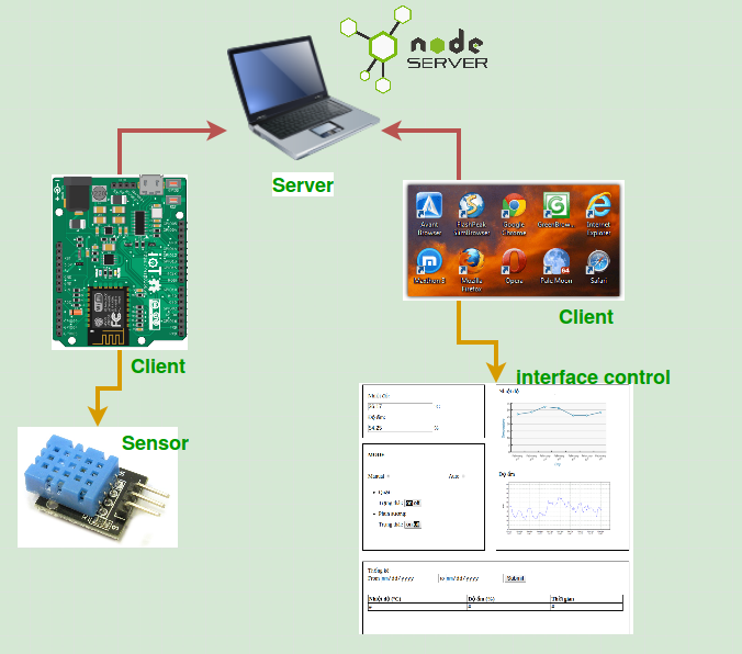
In practice, when designing the application, we should notice that users usually need a user-friendly graphical interface with many useful functions such as chart or graph illustrations, data extraction in desired time intervals, the database storing or 1-click device states control from PC,… Many larger and more complex projects will also need different methods to manage their connections and data.
To help you deal with those problems, we will guide you build a temperature and humidity monitoring application with capabilities of sending data back to a given web server and displaying it on a website. This is a simple, useful and easy IoT application, which will provide us with some basics on sensors data collecting and web server building.
Requirements
-
DHT11: Collecting the environment temperature and humidity data; Connecting and sending data to ESP8266.
-
ESP8266: Connecting to a WiFi Access Point and sending data to an HTTP server; displaying data on Arduino terminal screen.
-
Basic functions of HTTP server: Displaying current temperature and humidity on PC screen.
-
Advanced functions of HTTP server: Storing sensor data; interpreting users' requests and returning a result HTML file to view on web browsers.
Project Analysis
-
We will need a web server written in Javascript and implemented by Node.js and it will keep listening to a given port on PC. In this project, we are using port 8000.
-
ESP8266 and your PC must connect to the same WiFi Access Point. ESP8266 also need to know your PC’s IP to access the PC’s server. In this project, our PC’s IP is
192.168.1.102. -
After successfully connected to a WiFi Access Point, ESP8266 will read the current temperature and humidity data from DHT11 and send to the server every 2 seconds.
-
Using
GETmethod, web server can receive data from ESP8266. For example,http://192.168.1.102/update?temp=25&humd=80,192.168.1.102is the web server IP address,/updateis a path,temp=20andhumd=80contain the temperature "20°C" and humidity "80%". -
Web Server returns the HTTP Status = 200 (OK) and displays a logging window with current temperature and humidity.
-
Advanced Functions: — Web Server saves data in an array variable in RAM. — Web Server returns an
index.htmlfile to user with a special Javascript code to get the data stored in RAM and visualize it on screen.
Project-related Knowledge
It would be easier to understand if you already had some basics about:
-
Communicating between ICs with 1-Wire Protocol.
-
Using Javascript and Node.js to build a simple web server.
-
Building a simple HTML website to display sensor data.
However, do not get too worried when you have never done such things before, you’ll understand them more thoroughly while reading the next parts.
DHT11 Sensor and 1-Wire Communication Protocol
-
DHT11 is a widely used, low-cost and high-stability sensor and is usually used to measure the temperature and humidity of the environment. It uses 1-Wire Communication Protocol to send data to microcontroller. For more information, visit the manufacturer’s datasheet: Datasheet
-
1-Wire is a device communication bus system designed by Dallas Semiconductor Corp. that provides low-speed data, signaling, and power over a single conductor. One distinctive feature of the bus is the possibility of using only 2 wires: data and ground. Like other communication protocols, a signal sequence of 1-Wire contains 3 steps: request → respond → data reading.
A detailed signal diagram is shown below:
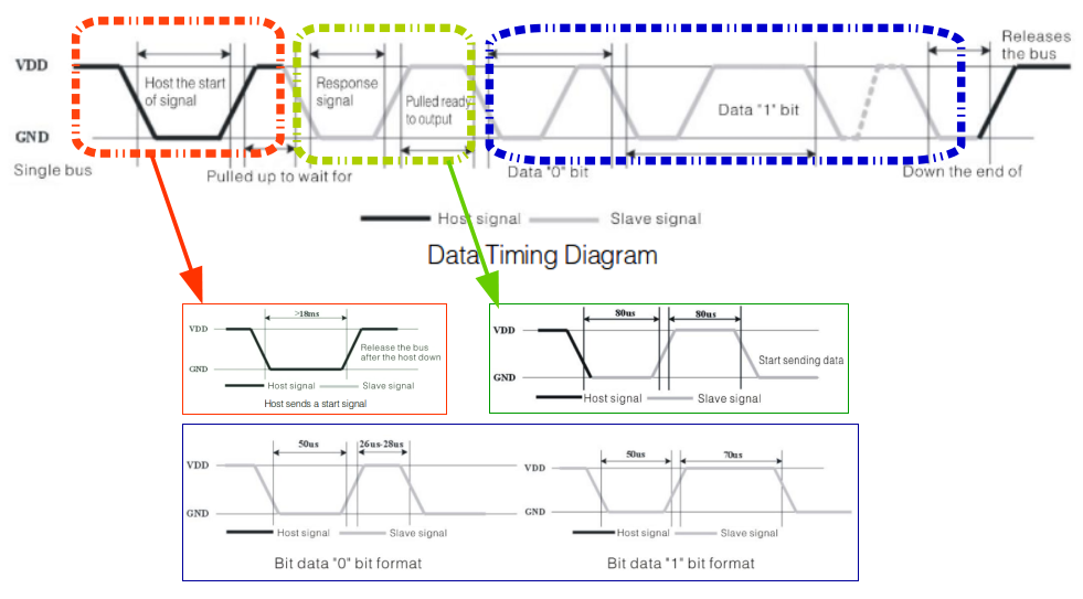
Summary:
-
If the Master (ESP8266) sends the
STARTsignal, DHT11 will transition from low-power mode to high-speed mode. -
DHT11 receives the signal and responds to the master, then the Master starts the data transmission.
-
During a signal period, DHT11 sends a 40 bits data packet to the bus.
-
If the Master wants to end the transmission, it will send a
STOPsignal and the process will stop.
For more information, visit maximintegrated.com
HTML Language
A popular website to help newbies learn HTML is w3school.com/HTML. But you shouldn’t dive into learning HTML at this moment because it would take a long time to completely master it. You only need to learn some basic features of HTML to complete this project.
Node.js and Javascript
To create a Node.js server, you need to know some basics of Javascript and Node.js. To learn Javascript, you can visit w3school.com/Javascript. A useful website for newbies to learn Node.js is codeschool.com
Building the Project:
Required Components
-
DHT11 sensor.
-
ESP8266 WiFi Uno Board.
-
Male-to-Female Jumper Wires.
-
5k Ohm Resistors.
-
USB micro-B cable.
Wiring
Using the following diagram to assemble the circuit.
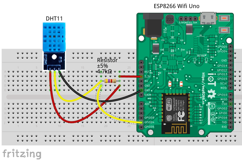
Server Nodejs
On Server side, we need to ensure that the server can serve many clients.
If path is:
-
/update: server will add new sensor data to database and display it on the screen. -
/get: server will return a JSON string of stored data. -
/: return theindex.htmlfile. -
The structure of stored array on RAM:
[{"temp": 25, "humd":80, time: "time"}, ...]
server.js source code
//---------------------------------------------------------------------------------------------
var fs = require('fs');
var url = require('url');
var http = require('http');(1)
var querystring = require('querystring');
var db = []; // Declare a database array variable.
//---------------------------------------------------------------------------------------------
// This function is used to handle client's request and return a response from server.
function requestHandler(request, response) {

    // An example request: http://192.168.1.7:8000/update?temp=30&humd=40
    var uriData = url.parse(request.url);
    var pathname = uriData.pathname;          // /update?
    var query = uriData.query;                // temp=30.5&hum=80
    var queryData = querystring.parse(query); // queryData.temp = 30.5, queryData.humd = 40
    //-----------------------------------------------------------------------------------------
    if (pathname == '/update') {
        var newData = {
            temp: queryData.temp,
            humd: queryData.humd,
            time: new Date()(2)
        };
        db.push(newData);
        console.log(newData);
        response.end();
    //-----------------------------------------------------------------------------------------
    } else if (pathname == '/get') {(3)
        response.writeHead(200, {
            'Content-Type': 'application/json'
        });
        response.end(JSON.stringify(db));
        db = [];
    //-----------------------------------------------------------------------------------------
    } else { (4)
        fs.readFile('./index.html', function(error, content) {
            response.writeHead(200, {
                'Content-Type': 'text/html'
            });
            response.end(content);
        });
    }
    //-----------------------------------------------------------------------------------------
}
var server = http.createServer(requestHandler);
server.listen(8000); (5)
console.log('Server listening on port 8000');
Explanation
| 1 | require is used to load necessary modules or libraries.
|
| 2 | This function will respond differently depending on the pathname. If pathname=/update, this function will create a newData variable and get data in client’s request. Then it will push data to db variable using db.push(newData) command and that data will be display on logging screen when using console.log(newData). Date() function helps us get current time and date. |
| 3 | Return the JSON format ('Content-Type': 'application/json') of db variable if pathname = /get, then it deletes value of db. response.end() function returns HTTP code = 200 (OK) |
| 4 | Return the index.html file if user doesn’t use /update and /get. fs library is used to read index.html file and assign that file’s content to content with fs.readFile('./index.html', function(error, content) command. response.writeHead(200, {'Content-Type': 'text/html' }) defines the HTTP code "200" and the response type "HTML" to read file on user’s browser. |
| 5 | Start the HTTP server and open port 8000 on server to listen for client’s request. |
Now, you should change to server.js directory and run node server.js on your terminal, then visit localhost:8000 on your web browser to view your index.html file. Or visit localhost:8000/update?temp=20&humd=60 to see the result on your logging screen.
{ temp: '20', humd: '60', time: 2017-08-21T16:56:23.358Z }
{ temp: '20', humd: '60', time: 2017-08-21T16:57:06.277Z }
{ temp: '20', humd: '60', time: 2017-08-21T16:57:17.708Z }
While doing the basic function above, you don’t need to understand the index.html and its Javascript code. Also, you’ve just handled the \update path, not \get or /\*. The \update is enough to run the basic function.
In the advanced sections, we are building a popular function of the application. That’s the data visualization on user’s web browser. To achieve that, we will create an index.html file with Javascript codes. Those Javascript codes will request server to return data every 2 seconds and illustrate it in graph.
index.html file
<!DOCTYPE html>(1)
<html>
<head>
<meta charset="UTF-8">
<title>DHT11</title>
<!-- Use a Javascript code at src destination to illustrate data in graph -->
<script type="text/javascript" src="https://canvasjs.com/assets/script/canvasjs.min.js"></script> (2)
</head>
<body>
<h1> 1. TEMPERATURE AND HUMIDITY MEASUREMENTS:</h><br> (3)
<h2> Temperature</h2> <input type="text" size="6" id="temp">°C<br>
<h2> Humidity</h2> <input type="text" size="6" id="humd">%<br>
<h1> 2. CHART OVER TIME: </h1><br>
<!-- Configure the graph's size via "ChartContainer" ID -->
<div id="ChartContainer" style="height: 300px; width:80%;"></div>
<script type="text/javascript">
function httpGetAsync(theUrl, callback) { (4)
var xmlHttp = new XMLHttpRequest();
xmlHttp.onreadystatechange = function() {
if (xmlHttp.readyState == 4 && xmlHttp.status == 200)
callback(JSON.parse(xmlHttp.responseText));
}
xmlHttp.open("GET", theUrl, true); // true for asynchronous
xmlHttp.send(null);
}
window.onload = function() {
var dataTemp = [];
var dataHumd = [];
var Chart = new CanvasJS.Chart("ChartContainer", {
zoomEnabled: true, // Enable this attribute to zoom in the graph.
title: {
text: "Temperature & Humidity" // Graph's tittle
},
toolTip: { // Display temperature and humidity simultaneously
shared: true
},
axisX: {
title: "chart updates every 2 secs" // X-axis label
},
data: [{
// Define the dataTemp's and dataHumd's attribute.
type: "line", // Choose "line" graph type.
xValueType: "dateTime", // Display "time" data on X axis.
showInLegend: true, // Display "temp" at graph legend.
name: "temp",
dataPoints: dataTemp // Choose the data source to plot. In this case, "dataTemp".
},
{
type: "line",
xValueType: "dateTime",
showInLegend: true,
name: "humd",
dataPoints: dataHumd
}
],
});
var yHumdVal = 0; // Declare a variable to store the humidity value on Y Axis.
var yTempVal = 0; // Declare a variable to store the temperature value on Y Axis.
var updateInterval = 2000; // The update interval, 2000ms = 2s
var time = new Date(); // Get current date.
var updateChart = function() {
httpGetAsync('/get', function(data) {
// Assign the value from localhost:8000/get to display on a textbox
document.getElementById("temp").value = data[0].temp;
document.getElementById("humd").value = data[0].humd;
// Print received values from localhost:8000/get to console
console.log(data);
// Update the time and get new temperature, humidity value.
time.setTime(time.getTime() + updateInterval);
yTempVal = parseInt(data[0].temp);
yHumdVal = parseInt(data[0].humd);
dataTemp.push({ // Push new data from server.
x: time.getTime(),
y: yTempVal
});
dataHumd.push({
x: time.getTime(),
y: yHumdVal
});
Chart.render(); // Convert the data to graph on screen.
});
};
updateChart(); // Run the first time
setInterval(function() { // Update the graph every "updateInterval" seconds.
updateChart()
}, updateInterval);
}
</script>
</body>
</html>Explanation
| 1 | Some basic tags to set up your HTML file in the beginning:
|
| 2 | Use CanvasJS Chart to draw temperature and humidity graph. |
| 3 | Create 2 text boxes in <h1> heading to display current value of temperature and humidity. Each text box has a unique id to get sensor data from server. The °C means °C. |
| 4 | Get data from server using this function. |
Graph Analysis
-
Using
<script> JS code </script>tag in your HTML file, you can get data from server and visualize it in graph. -
You can get data by executing
httpGetAsync()function. This function useXMLHttpRequestobject to get data from server without reload webpage. Because the dataxmlHttp.responseTextreturned fromlocalhost:8000/getis formatted in JSON, you need to useJSON.parse()to convert it toObjecttype.
| ESP8266 must have sent data to server, or localhost:8000/get won’t return values. |
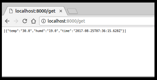
localhost:8000/get-
Use
window.onload = function()to reload the graph, we have explained at the end of each line.
| Visit canvasjs.com/javascript-charts/ for more graphs and choose suitable ones for your project. |
The finished HTML file
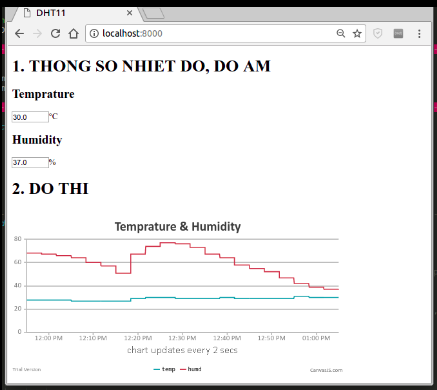
Code on ESP8266
ESP8266 uses HTTPClient library to make a connection and send DHT11 temp and humd data to web server via GET method.
Preparation:
-
A local WiFi Access Point’s SSID and Password.
-
An IP and Port of Web Server.
-
A library to help us get data from DHT11. Because of the popularity of the DHTXX sensors, many libraries have been released to support users. In this project, we are using the
DHT sensor libraryof Adafruit.
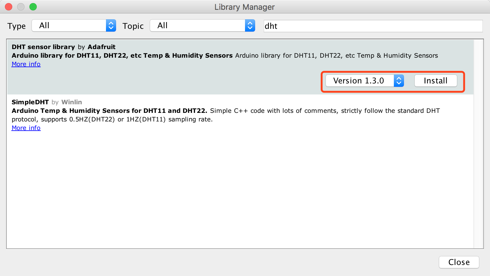
Source code on ESP8266
#include <DHT.h>            // Include the DHT library to read DHT11 sensor data.
#include <ESP8266WiFi.h>    // Include this library to configure ESP8266 as a client.
#define DHTPIN 4            // Define the GPIO 4 to receive data from DHT11.
#define DHTTYPE DHT11       // Define the type of DHT sensor. In this case, DHT11.

DHT dht(DHTPIN, DHTTYPE);
WiFiClient client;                        // Declare the "client" variable of "WiFiClient" type.
const char* ssid = "YOUR-WIFI-SSID";      // Declare the SSID or your WiFI Access Point's name.
const char* password = "YOUR-WIFI-PASS";  // Declare the WiFi password of the above WiFi AP.
const char* server = "Your-local-IP";     // Declare your web server IP or your PC's IP.
const int port = 8000;                    // Declare the port on server to be opened for listening.
const int sendingInterval = 2 * 1000;     // Declare the interval time in microseconds between two successive measurements.

void setup() {
  Serial.begin(115200);
  dht.begin();                            // Initiate the DHT11 sensor.
  Serial.println("Connecting");


  // Configure ESP8266 as a Station and connect to a WiFi AP. Continuously print . on the terminal if it hasn't successfully connected to our WiFi AP.
  WiFi.begin(ssid, password);
  while (WiFi.status() != WL_CONNECTED) {
    Serial.print(".");
    delay(100);
  }
  Serial.println("\r\nWiFi connected");
}

void loop() {

// Read the temperature (in Celsius Scale) and humidity. If the sensor fails to read, print out an error message and skip the current loop.
  float temp = dht.readTemperature();
  float humi = dht.readHumidity();
  if (isnan(temp) || isnan(humi)) {
    Serial.println("Failed to read from DHT sensor!");
    return;
  }

  if (client.connect(server, port)) {           // Initiate a connection to a server with a given IP and PORT.
  //---------------------------------------------------------------------------------------
    String req_uri = "/update?temp=" + String(temp, 1) + "&humd=" + String(humi, 1);
    client.print("GET " + req_uri + " HTTP/1.1\n" + "Host: "+ server +"\n" + "Connection: close\n" + "Content-Length: 0\n" +"\n\n");   (1)
  //---------------------------------------------------------------------------------------

  // Convert the temp and humi from float to string and print it on Arduino serial terminal
    Serial.printf("Nhiet do %s - Do am %s\r\n", String(temp, 1).c_str(), String(humi, 1).c_str());
  }
  client.stop();                          // Disconnect from server.

  delay(sendingInterval);
}| 1 | After successfully connected to server, ESP8266 will use client.print() command to send a data packet to server.
A packet example:
|
After reviewing your source code:
You can use curl command to view the HTTP request headers and other things:
curl -v http://192.168.1.7:8000/update?temp=28.0&humd=45.0. Here is the output:
name@yourname:~$ curl -v http://192.168.1.7:8000/update?temp=28.0&humd=45.0
[1] 9277
name@yourname:~$ *   Trying 192.168.1.7...
* Connected to 192.168.1.7 (192.168.1.7) port 8000 (#0)
> GET /update?temp=28.0 HTTP/1.1    // > Message sent from ESP8266
> Host: 192.168.1.7:8000
> User-Agent: curl/7.47.0
> Accept: */*
>                                  // < Message sent from server
< HTTP/1.1 200 OK
< Date: Wed, 23 Aug 2017 17:22:49 GMT
< Connection: keep-alive
< Content-Length: 0
<
* Connection #0 to host 192.168.1.7 left intact
The result will be displayed on Arduino and PC logging screen.
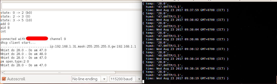
Extending your application
ESP8266 Web Server
You should try to add some new features to the project. Here are some ideas:
-
Measure and display temperature and humidity in real-time
-
Illustrate in graph the sensor data over time.
-
Have 2 modes: Auto and Manual.
-
The Auto mode: turns your fan on automatically when the temperature > 35ºC or turn on a humidifier when the humidity is below 50%.
-
The Manual mode: controls your fan and humidifier manually with ON/OFF switch on web interface.
-
-
Display temperature and humidity history in a specified date interval, from aa/bb/cccc to xx/yy/zzzz.
This is an example of a graphical user interface:
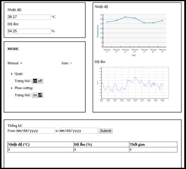
Summary
Upon completion of this project, you will have an overview of building a complete sensors data logging project as well as building a web server to serve the clients from scratch. This will help you lay the foundations for many larger data logging and analyzing projects in the future.
WiFi configuration on ESP8266
When prototyping an idea with ESP8266, people usually focus on the features of that ideas, not the user’s experience. So a fully-functioning prototype could lack of a user interface, a keyboard or a touchscreen,… That would lead to some inconveniences for users.
For example, whenever an ESP8266 wants to connect to a new WEP/WPA/WPA2 WiFi Access Point, we must manually provide the AP’s configuration, SSID and password in the source code and compile those code into a new binary file on PC. Then using a USB cable, we upload that file to the device just to change the WiFi AP!
To deal with those problems, ESP8266 provides some user-friendly alternatives to simplify the WiFi set-up process. In this chapter, we are introducing SmartConfig, WPS and WiFi Manager.
Smartconfig
Introduction
SmartConfig protocol helps users connect ESP8266 devices to a WiFi network through simple configuration on a smartphone. With this protocol, a smartphone sends UDP packets to the Wi-Fi Access Point (AP), and encodes the SSID and password into the Length field of a sequence of UDP packets. The ESP8266 device can reach those packets, decode the information, get the SSID and password from decoded data and connect it to the network.
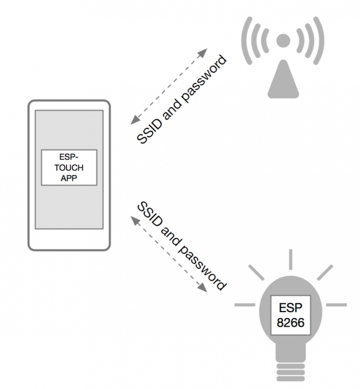
We should know that, when a smartphone connects to a secured wifi network, all the data between your router and your smartphone will be encrypted during the transmission. So any other devices, which are not connected to the network at the beginning, cannot decrypt and read the data packets. So how can a smartphone app send the information to the unconnected devices directly? The solution is based on 2 things:
-
ESP8266 is capable of
sniffingout all the packets being passed around, even the encrypted packets! -
The content of an encrypted packet in a WiFi network cannot be read, but the length field of that packet is a constant and ESP8266 can reach that. For example, we have an unencrypted packet "A" with the length of
x. When "A" is encrypted into "B",x + nis the new length of "B" andnis a constant.
Here is the ESP-TOUCH operation process sending SSID and password to an ESP8266 device:
-
Enable SmartConfig function on ESP8266 device and it starts sniffing all the packets.
-
Connect your smartphone to router.
-
Input the router’s SSID and password on phone app and it will broadcast a packet with random contents with encoded SSID and password in Length field.
-
For example, you have a network with SSID
mynetwork. The first lettermcorresponds to109in ASCII code. To broadcast letterm, that app will send a packet which has random contents and a length of 109 to router. And the process is repeated to broadcast each letter in the SSID name. This method is also used to broadcast password, smartphone’s IP address and other letters to ESP8266 devices.
-
-
ESPTOUCH protocol could encrypt transmitted data in the process above but the principle is the same.
-
ESP8266 devices will sniff out those packets whose length changes over time, then decrypt the data and extract the SSID, password and other related information.
-
When ESP8266 has successfully connected to wifi network, it will connect to user’s smartphone using the decoded IP address and send a message to notify the app of its successful connection.
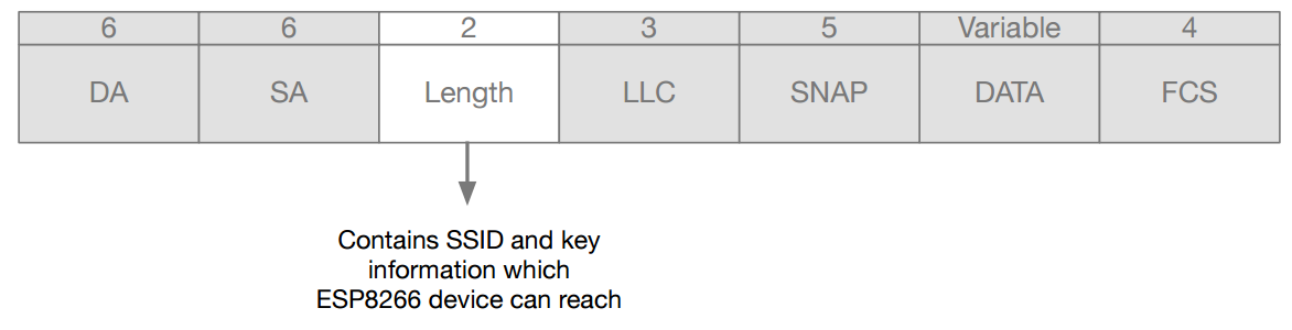
NOTE:
-
It will take longer time to establish the connection with greater distance.
-
If the device cannot connect to the router within a specified time period, the App will return a configuration failure message. Users can define the overtime settings through
esptouch_set_timeout(uint8 time_s). -
Your ESP8266 device should be configured as a STATION when it connects to network using SmartConfig.
-
Users can configure multiple devices to connect to the same router simultaneously.
-
ESPTOUCH supports 802.11n and 2.4GHz wireless routers .
Running SmartConfig on ESP8266
In the following example, our ESP8266 is connecting to a wifi network using SmartConfig and on Android, we are using SmartConfig app to input the SSID and its password. You can easily search for this app as well as other similar app on Play Store (Android) and iTunes (iOS).
First, you need to upload the compiled code to ESP8266. The key command in this program is the WiFi.beginSmartConfig() line and it’s provided in ESP8266WiFi library. This command allows the device to enter SmartConfig mode, sniff out the desired packets and decrypt them to connect to a wifi network.
After uploading your sketch, you should hold the GPIO0 button in 3 seconds, the built-in LED will blink faster and your device will enter SmartConfig mode. Connect your smartphone to a desired wifi network, open SmartConfig app, input the SSID and PASSWORD (if any), and press CONFIRM.
Code
#include <Arduino.h>
#include <ESP8266WiFi.h>
#include <Ticker.h>
#include <time.h>

#define PIN_LED 16
#define PIN_BUTTON 0

#define LED_ON() digitalWrite(PIN_LED, HIGH)
#define LED_OFF() digitalWrite(PIN_LED, LOW)
#define LED_TOGGLE() digitalWrite(PIN_LED, digitalRead(PIN_LED) ^ 0x01)

Ticker ticker;

/* Button state check function*/
bool longPress()
{
  static int lastPress = 0;
  if (millis() - lastPress > 3000 && digitalRead(PIN_BUTTON) == 0) { // If button is pressed in more than 3 seconds then...
    return true;
  } else if (digitalRead(PIN_BUTTON) == 1) {                         //  If button is pressed in lest than 3 seconds then...
    lastPress = millis();                                            // `lastPress` variable is assigned when this condition is true.
  }
  return false;
}

void tick()
{
  int state = digitalRead(PIN_LED); // Get current LED's state (on GPIO 16)
  digitalWrite(PIN_LED, !state);    // Invert LED's state.
}

bool in_smartconfig = false;        // This variable stores the state of smartconfig mode.
                                    // "True" means this mode is running and vice versa.
//

/* Start Smartconfig mode */
void enter_smartconfig()
{
  if (in_smartconfig == false) {          // If smartconfig state variable is "false" i.e the smartconfig mode is currently off, then
    in_smartconfig = true;                // Assign "true" value to smartconfig state variable.
    ticker.attach(0.1, tick);             // Blinking in 0.1 seconds period.
    WiFi.mode(WIFI_STA);                  // Configure ESP8266 as Station mode.
    WiFi.beginSmartConfig();              // Start Smartconfig mode.
    Serial.println("Enter smartconfig");  // Print message "Enter smartconfig" to terminal's screen.
  }
}

/* Exit Smartconfig mode*/
void exit_smart()
{
  ticker.detach();                                // Stop blinking LED.
  LED_ON();                                       // Turn LED ON.
  in_smartconfig = false;                         // Reset button's state variable..
  Serial.println("Connected, Exit smartconfig");  // Print message to terminal.
}

/* Set up the serial connection, input and output */
void setup() {
  Serial.begin(115200);           // Baudrate = 115200
  Serial.setDebugOutput(true);    // Use this to enable printing debug log to terminal via serial connection.
  pinMode(PIN_LED, OUTPUT);       // Configure the OUTPUT mode for LED's GPIO. .
  pinMode(PIN_BUTTON, INPUT);     // Configure the INPUT mode for the built-in BUTTON's GPIO.
  Serial.println("Setup done");   // Print message "Setup done" to the terminal.
}

/* Main program */
void loop() {
  if (longPress()) {              // Call longPress() to check button's state
    enter_smartconfig();          // If "true", enter smartconfig mode
  }
  if (WiFi.status() == WL_CONNECTED && in_smartconfig && WiFi.smartConfigDone()) {
                                  // Check WiFi connection status and smartconfig's state
    exit_smart();                 // When your device has successfully connected to WiFi, exit smartconfig mode.
  }
  if (WiFi.status() == WL_CONNECTED) {
    //Your program will be executed here when your device has been connected to WiFi.
  }
}
After reviewing your code:
WPS
What is WPS?
This section will introduce the WPS concept, its usage and how to use it on ESP8266.
Wi-Fi Protected Setup (WPS; originally, Wi-Fi Simple Config) is a network security standard to create a secure wireless home network and make it easy to add new devices to an existing network without searching and entering long passphrases. WPS is available to use only if both the router and your device support the WPA/WPA2 security protocol.
There are three primary approaches to network set up within Wi-Fi Protected Setup: push-button, PIN entry, and NFC - Near Field Communication (not popular yet). We are using push-button to set up WiFi in this tutorial.
Here is the process using push-button:
-
First, push the WPS button on router and let it enter a special security mode. This mode allows connection requests from WPS-supported devices.
-
Next, push the WPS button, either an actual or virtual one, on the wireless client device. This action allows that device to connect to a router using WPS. Routers from different manufacturers have a different timeout, usually from 1 minute to 5 minutes. If it takes too long and exceeds this timeout, the connection using WPS fails.
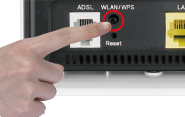
Connect to WiFi network on ESP8266 using WPS
The WiFi.beginWPSConfig() function in ESP8266WiFi library help ESP8266 to configure and connect to a network using WPS. This example will configure WPS on ESP8266 without any push-buttons.
- You can only connect to wifi using WPS only if your ESP8266 is in STA (station) mode.

- WPS mode must have already been configured on your router.
Code
#include <ESP8266WiFi.h>

void setup()
{
  // Set up the initial condition
  Serial.begin(115200);
  WiFi.mode(WIFI_STA);
  // Connect to a known WiFi AP, whose SSID and password is stored on ESP8266's FLASH memory.
  WiFi.begin("", "");
  delay(4000);


  // Check the WiFi connection. If not connected yet, use WPS to connect.
  // Your router should be in WPS mode during these commands.
  while (WiFi.status() != WL_CONNECTED)
  {
    Serial.println("\nAttempting connection ...");
    WiFi.beginWPSConfig();
    delay(6000);
  }
  // After successful connection, print out the local IP, SSID and MAC address of your device.
  Serial.println("\nConnection already established.");
  Serial.println(WiFi.localIP());
  Serial.println(WiFi.SSID());
  Serial.println(WiFi.macAddress());
}

void loop()
{
  // Main program
}
After reviewing your source code:
Wifi Manager
The WiFiManager library allows you to easily manage the Wi-Fi connection in your ESP8266 projects via a user-friendly web interface. By starting the ESP8266 in access point mode (AP mode) with its own DNS and WebServer, you can connect to it using any WiFi device with a browser (PC, smartphone, tablet). Any connections to that AP will be redirected to a configuration portal. Using this portal, you can configure ESP8266 to scan WiFi, choose one of the APs scanned, enter password and save it for later use.
How it works?
-
When your ESP8266 starts up, it sets it up in Station mode and tries to connect to a previously saved Access Point.
-
If that connection is unsuccessful (previous APs are offline, or wrong password, or perhaps there is no known network available), it moves the ESP into Access Point mode and spins up a DNS and a Web Server (with default ip 192.168.4.1). This DNS typically points to itself, but you can configure it to point to another domain.
-
You can use any wifi enabled device with a browser (computer, phone, tablet) and connect to that newly created Access Point. This AP’s name is default and it doesn’t require a password to log in:
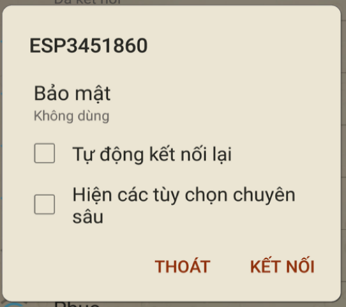
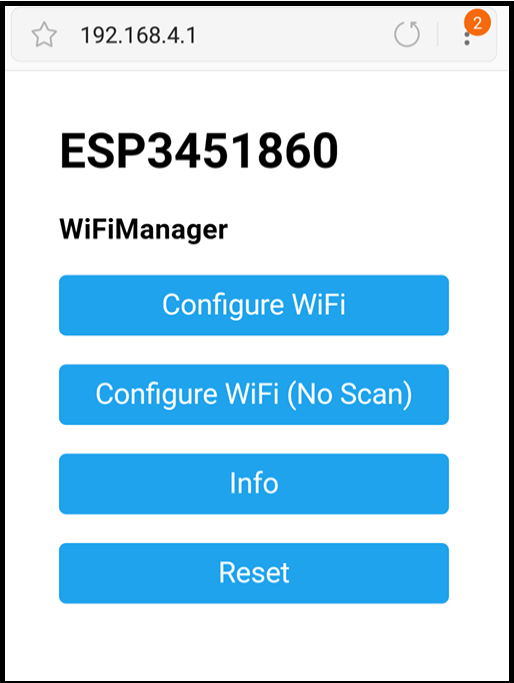
-
When the configuration portal of ESP8266’s AP at "192.168.4.1" finishes loading, choose "Configure Wifi" or "Configure Wifi (no scan)" to set up a new WiFi connection:
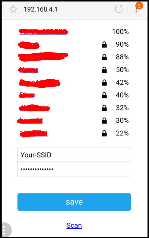
-
Choose a WiFi AP and enter its password.
-
If success, the Web Server on ESP8266 will turn off and the ESP8266 AP becomes unavailable. If fail to connect, you need to reconnect to ESP8266 AP, choose another AP and repeat steps above.
Preparation
-
Install WiFiManager library: github.com/tzapu/WiFiManager.
-
How to install a new library? Follow Install arduino library
Source Code
#include <ESP8266WiFi.h>          //https://github.com/esp8266/Arduino

//Include neccessary libraries.
#include <DNSServer.h>
#include <ESP8266WebServer.h>
#include "WiFiManager.h"          //https://github.com/tzapu/WiFiManager

void configModeCallback (WiFiManager *myWiFiManager)
{
  Serial.println("Entered config mode");
  Serial.println(WiFi.softAPIP());
  Serial.println(myWiFiManager->getConfigPortalSSID());
}

  // Initialize the serial communication and connect to wifi using WiFiManager.
void setup()
{
  Serial.begin(115200);

  // Declare the "wifiManager" variable. It is a 'WiFiManager' class and is defined in "WiFiManager.h".
  WiFiManager wifiManager;

  // Uncomment this command to reset settings to default.
  // wifiManager.resetSettings();

  // Set up a callback. When your device fails to connect to a known AP, it calls this callback
  // and starts its own AP station with a default SSID "ESP+chipID".
  wifiManager.setAPCallback(configModeCallback);
  if (!wifiManager.autoConnect())
  {
    Serial.println("failed to connect and hit timeout");
  // If failed to connect, reset your device and re-connect.
    ESP.reset();
    delay(1000);
  }
  // Print this message to terminal screen when your device has successfully connected to WiFi.
  Serial.println("connected...yeey :)");

}

void loop()
{
  // Main program.
}
After reviewing your code:
Extending your knowledge:
There are many available useful features in WiFiManager library such as configuration portal timeout, custom IP configuration, HTML, CSS or Javascript,…
You can find out further information on their GitHub page: github.com/tzapu/WiFiManager
Summary
When you build an IoT system in real life, you will face many challenges. One of the most important challenges is making your product easy-to-use, easy-to-configure and secure during data transmission. You should consider your purpose and your product’s functionalities to choose an appropriate solution to configure WiFi connection.
For example, if your device contains buttons or a smartphone app, you should consider choosing SmartConfig or WPS. Or, if you are making a smart light bulb with the ability to control over WiFi, then WiFIManager will be the most suitable solution. It’s up on you!
MQTT

MQTT stands for Message Queuing Telemetry Transport and it is a publish/subscribe, extremely simple and lightweight messaging protocol, designed for constrained devices and low-bandwidth, high-latency or unreliable networks.
These principles also turn out to make the protocol ideal of the emerging “machine-to-machine” (M2M) or “Internet of Things” world of connected devices, and for mobile applications where bandwidth and battery power are at a premium.
Facebook has implemented MQTT in Facebook Messenger for online chat
There are many free online resources to help gain an in-depth understanding of MQTT. In this section, we will introduce some basics of MQTT: "subscribe", "publish", "qos", "retain", "last will and testament (lwt)"
Publish, subscribe
The clients in an MQTT system connects to an MQTT server called the broker. Each client has to "subscribe" to some topics. For example, "/client1/channel1", "/client1/channel2",… This process is similar to the subscription feature on Youtube. When each client "publishes" a message to the broker, the broker will deliver all messages with the matching topic to the client.
QoS
You will have 3 levels of QoS (Qualities of service) when you "publish" and "subscribe":
-
QoS0 : The message is delivered at most once to the receiver. This message is only guaranteed by the underlying TCP protocol and this is often called "fire and forget".
-
QoS1 : The message is always delivered at least once to the receiver. If the sender does not receive an acknowledgment, the message is sent again until an acknowledgment is received. As a result, the same message can be sent multiple times, and the receiver might process it multiple times.
-
QoS2 : The message is always delivered exactly once to the receiver, and this QoS is a 4-step handshake transmission.
A message can be sent in any QoS mode and the clients can also subscribe in any QoS mode - i.e., the clients will select the highest QoS available to receive the message.
For example, if a message is published in QoS2 and a client subscribes with QoS0, the broker will send that message to client with QoS0. Another client, who subscribes to this topic with QoS2, will be sent with QoS2 from broker.
Another example, if a client subscribes with QoS2 and the message is sent in QoS0, that client will be sent a message in QoS0 from broker.
The higher QoS, the more reliability, latency and bandwidth.
Retain
If the retained flag is set to true, the broker MUST store the last retained message and the corresponding QoS. That message will be sent to every new subscriber in future. Each client that subscribes to a topic pattern, which matches the topic of the retained message, will receive the last message with RETAIN = 1 immediately after subscribing. If the Broker receives a new message with QoS = 0 and RETAIN = 1, it will delete all stored retained message and save the new one. For each topic only one retained message will be stored by the broker.
When publishing a message to clients, the brokers must set the RETAIN to 1 to notify the successful subscribing to client (it is similar to the ACK message when the subscribing is successful). If we don’t need to notify the result of subscribing process. set RETAIN to 0.
LWT
LWT messages are not really concerned about detecting whether a client has gone offline or not (that task is handled by keepAlive messages). LWT messages are about what happens after the client has gone offline.
An example
I have a sensor, which sends crucial data, but very infrequently. It has formulated a last will statement in topic: /node/gone-offline with its unique id. I also have subscribed to the the topic node/gone-offline, which will send a SMS to my phone every time a message is published on that channel.
During normal operation, the sensor will keep the connection to the MQTT-broker open by sending periodic keepAlive messages. If the sensor goes offline, the connection to the broker will time out, due to the lack of keepAlives.
This is where LWT comes in: If no LWT is specified, the broker doesn’t care and just closes the connection. In our case however, the broker will execute the sensor’s last will and publish the LWT-message "id" to node/gone-offline. Because I have subscribed to that topic, the message will then be sent to phone and I will be notified of the sensor’s ID via SMS so that I can check up on what’s going on.
In short
Instead of just closing the connection after a client has gone offline, LWT messages can be leveraged to define a message to be published by the broker on behalf of the client, since the client is offline and cannot publish anymore.
MQTT Client
Như chúng ta đã tìm hiểu ở phần trước, 2 thành phần publisher và In the previous section, we have discovered 2 fundamental components of MQTT protocol: "publisher" and "subscriber". an MQTT Client doesn’t transmit directly to other clients, every sent packet is distributed to an appropriate subscriber by an MQTT Broker. In this section, we are introducing some common MQTT Clients to demonstrate the MQTT concepts you have learned. We are also introducing some free and popular MQTT Broker: test.mostquitto.org and cloudmqtt.com.
MQTT Lens
Overview
MQTT Lens is a Chrome Extension and it uses Chrome to connect to an MQTT Broker and tests the publish/subscribe features of MQTT. This is a very useful tool to test the connection and transmission to an MQTT Broker.
Here are some information about MQTT Lens:
Type |
Chrome App |
License |
MIT |
Operating Systems |
Windows, Linux & MacOSX |
Website |
"https |
Setup
We will using this tools to connect to an MQTT Broker service at iot.eclipse.org in the following steps:
-
Step 1: Install the Chrome Web Browser, log in to your Google account, visit chrome.google.com/webstore/category/extensions and type "MQTTlens" in the search box.
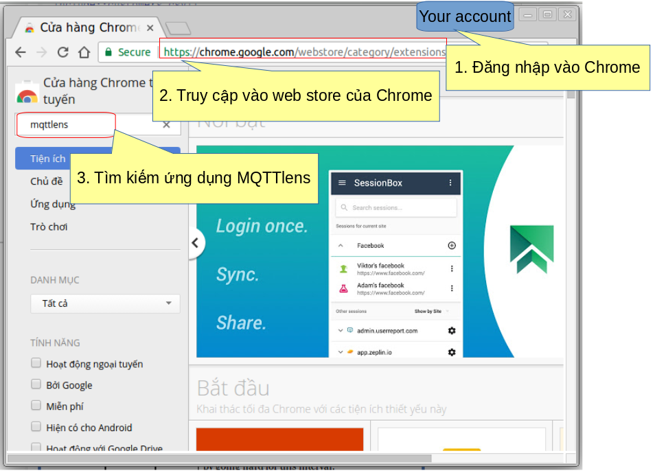
-
Step 2: Add to Chrome and run MQTT lens.
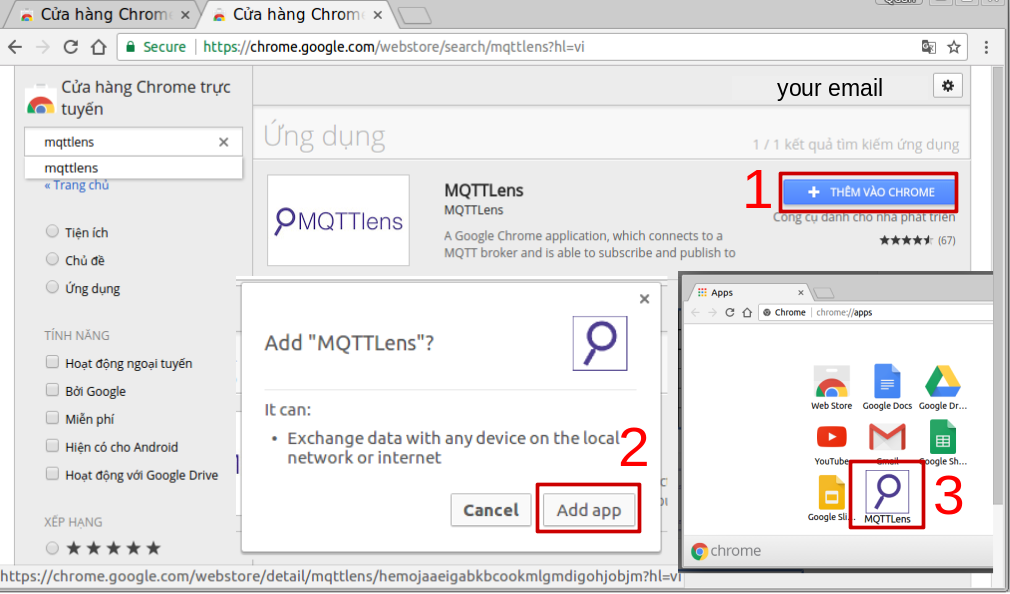
-
Step 3: Add a new connection to Eclipse MQTT Broker service.
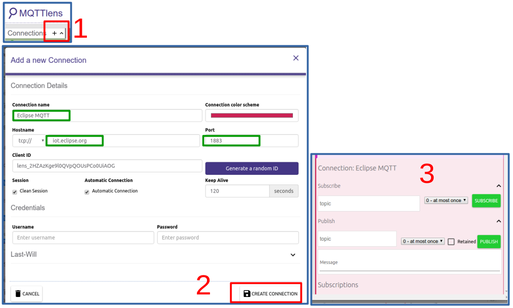
Explanation
We are adding a connection named "eclipse MQTT" to MQTT Broker host at iot.eclipse.org. This broker distributes data between clients and listens on port 1883( This port uses MQTT protocol and doesn’t encrypt data. To use other ports, visit test.mosquitto.org for more information).
This connection subscribes to the topic Home/garden/sensor/# (The # symbol allows it to subscribe Home/garden/sensor/1 , Home/garden/sensor/2 , etc). Then we publish a packet with a message: "Temp in garden: 27degree Celcius " to topic Home/garden/sensor/1 .
Result: In the Subscription panel, the MQTT Lens shows the received messages because it has subscribed to topic Home/garden/sensor/#
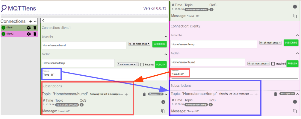
Extensions
Create more connections to subscribe and publish message with Eclipse Broker service and test the QoS and LWT.
MQTT.js
MQTT.js is an MQTT Client library written in JavaScript and Node.js platform. And it supports MQTT Over Websocket (MOW)
MQTT.js is an opensource project, you can get the latest release at github.com/mqttjs/MQTT.js.git
Setup
Step 1: The first, you we have to check the the operating system supported by Node.js before install MQTT.js. Install Node.js before installing MQTT.js. You can download here: nodejs.org/en/
Step 2: Create a Node.js project: We suggest creating a new folder for this project to store and conveniently manage NodeJS modules and .js file. Navigate to this folder and open Terminal (on Linux OS) or Command Prompt (on Windows OS) and run:
npm init
After running this command, you will have to provide some basic project information such as name, version, keywords, authors,… When you finish, a new file named package.json will be created in your project folder. This file contains the information you provided above and the package you will use later.
Step 3: Install MQTT.js:
Run:
npm install mqtt --save
When the installation finishes, you can use mqtt module to connect a Client to a Broker, publish message or subscribe to a topic. All the associated files of the mqtt module are stored in folder node_modules of project folder.
To understand how MQTT.js works, in next step, we are adding 2 new JavaScript files client-a.js and client-b.js to subscribe and publish messages.
Step 4: Create 2 new clients to subscribe and publish separately:
Those clients are connected to the same MQTT Broker. Client A subscribes to the topic /client-a/sub and if any messages are published to this topic, client A will publish message Hello from client A to topic /client-b/sub and then close connection and exit. The other client subscribes to the topic /client-b/sub and if any messages are published to this topic, client B will close connection and exit. After connecting to the broker, client B will immediately publish a message Hello from client B to the topic /client-a/sub.
Client A’s source code
// declare a "mqtt" variable to use mqtt module's features.
var mqtt = require('mqtt')
// declare a "client" variable and use the "connect" attribute to connect to a MQTT broker with hostname mqtt://iot.eclipse.org
var client = mqtt.connect('mqtt://iot.eclipse.org')
// This function subscribes to a topic after successfully connecting to broker.
client.on('connect', function() {
    console.log('Client A connected')
    // subscribe to the topic /client-a/sub
    client.subscribe('/client-a/sub')
})
// This function sends a message to subscribed topic.
client.on('message', function(topic, message) {
    // print to console a "string" type message.
    console.log(message.toString())
    // publish the message 'Hello from client A' to topic /client-b/sub
    client.publish('/client-b/sub', 'Hello from client A')
    // disconnect from server
    client.end()
})
console.log('Client A started')
Client B’s source code
// declare a "mqtt" variable to use mqtt module's features.
var mqtt = require('mqtt')
// declare a "client" variable and use the "connect" attribute to connect to a MQTT broker with hostname mqtt://iot.eclipse.org
var client = mqtt.connect('mqtt://iot.eclipse.org')
// This function will subscribe to a topic after successfully connecting to broker.
client.on('connect', function() {
    console.log('Client B connected')
    // subscribe to the topic /client-b/sub
    client.subscribe('/client-b/sub')
    // publish the message 'Hello from client B' to topic /client-a/sub
    client.publish('/client-a/sub', 'Hello from client B')
})
client.on('message', function(topic, message) {
    // print to console a "string" type message.
    console.log(message.toString())
    // disconnect from server
    client.end()
})
console.log('Client B started')
The result is shown below:
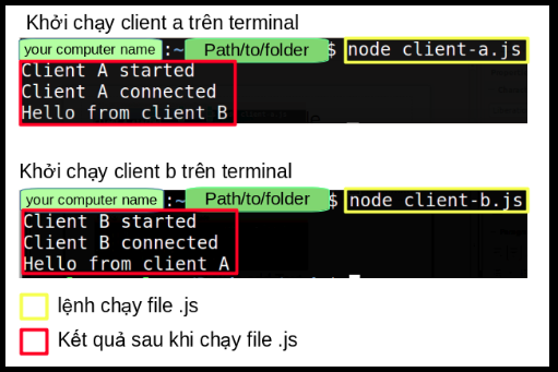
Furthermore, MQTT.js provides many commands to interact with Broker via Terminal. To do this, you need to install MQTT.js as a global module by using:
npm install mqtt -g.
You can open 2 terminals to test the codes. The 1st terminal subscribes to the topic "topicA" by running:
mqtt sub -t 'topicA' -h 'test.mosquitto.org' -v
The 2nd terminal publishes a message "Hello subscriber" to "topicA":
mqtt pub -t 'topicA' -h 'test.mosquitto.org' -m 'hello subscriber'
The options:
-
-t: MQTT topic, pushlish a message. -
-h: Specifies the server will connect -
-m: Sends a message using the command line. -
-v: verbose, The option allows you to record the activity log of the files in the configuration file.
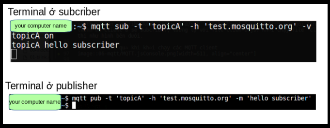
If you need help on other APIs of MQTT.js, run: mqtt help [command].
|
ESP8266 MQTT Client
There are many MQTT library for ESP8266 on Arduino IDE and in this section, we are using 2 popular libraries: PubSubClient and ESP8266MQTTClient
PubSubClient
In this section, we are connecting ESP8266 WiFi Uno to a Broker using PubSubClient library.
-
Step 1 : Download PubSubClient library at github.com/knolleary/pubsubclient and include it in the Arduino IDE. You can also import this library to Arduino IDE by searching the library with the keyword
PubSubClient, authorNick O'Learyand install it. -
Step 2 : Compile the following source code for ESP8266.
#include <ESP8266WiFi.h>
#include <PubSubClient.h>

const char* ssid = "........";
const char* password = ".........";
const char* mqtt_server = "broker.mqtt-dashboard.com";

WiFiClient espClient;
PubSubClient client(espClient);

void setup() {
  pinMode(16, OUTPUT);
  Serial.begin(115200);
  // Setup wifi connection and print the ESP8266's IP to terminal.
  setup_wifi();
  // Setup MQTT server "broker.mqtt-dashboard.com" and listen to client on port 1883.
  client.setServer(mqtt_server, 1883);
  // Call "callback" function to publish/subscribe
  client.setCallback(callback);
  // Call "reconnect()" function to restart the connection to server when it losts connection.
  reconnect();
}

void setup_wifi() {
  delay(10);
  Serial.println();
  Serial.print("Connecting to ");
  Serial.println(ssid);
  // Connect to a given WiFi
  WiFi.begin(ssid, password);
  // Print . during WiFi connecting process
  while (WiFi.status() != WL_CONNECTED) {
    delay(500);
    Serial.print(".");
  }
  // Print "WiFi connected" and ESP8266's IP to terminal
  Serial.println("");
  Serial.println("WiFi connected");
  Serial.println("IP address: ");
  Serial.println(WiFi.localIP());
}

void callback(char* topic, byte* payload, unsigned int length) {
  // Print the topic's header and content published from MQTT lens
  Serial.print("Message arrived [");
  Serial.print(topic);
  Serial.print("] ");
  for (int i = 0; i < length; i++) {
    Serial.print((char)payload[i]);
  }
  // Verify the data from topic "ESP8266/LED_GPIO16/status".
  // If the string is "ON", turn on the LED. And vice versa
  if ((char)payload[0] == 'o' && (char)payload[1] == 'n') //on
    digitalWrite(16, LOW);
  else if ((char)payload[0] == 'o' && (char)payload[1] == 'f' && (char)payload[2] == 'f') //off
    digitalWrite(16, HIGH);
  Serial.println();
}

void reconnect() {
  // Keep attempting to connect to MQTT broker until the connection is recovered.
  while (!client.connected()) {
    Serial.print("Attempting MQTT connection...");
    if (client.connect("ESP8266")) {
      Serial.println("connected");
      // publish "Connected!" message to topic ESP8266/connection/board
      client.publish("ESP8266/connection/board", "Connected!");
      // Subscribe to topic ESP8266/LED_GPIO16/status
      client.subscribe("ESP8266/LED_GPIO16/status");

    } else {
      // Print the client's state if it can't connect to MQTT broker.
      Serial.print("failed, rc=");
      Serial.print(client.state());
      Serial.println(" try again in 5 seconds");
      // delay 5 seconds
      delay(5000);
    }
  }
}

void loop() {
  // Check the ESP8266 connection. Reconnect to broker if connection isn't ready yet
  if (!client.connected()) {
  if (!client.connected()) {
    reconnect();
  }
  client.loop();
}
Source code explanation:
We declare a espClient variable in WiFiClient class. It is an MQTT Client and use the attributes of PubSubClient library.
The setup() function configures the ESP8266 as a station and connects to wifi. In addition, the setup () function will also auto-reconnect to MQTT Broker when a connection is lost. The reconnect() subscribes to the given topic and publishes its state to another topic.
The callback() function gets a message from publishers and then sent it the topic. The client, which has subscribed to that topic earlier, receives and checks the message to control the LED on GPIO16.
The loop() function connects the Client (ESP8266) to a Broker. Then it publishes a message and subscribes to a topic.
The client.loop() function tests the connectivity by using KEEP_ALIVE packet and returns a boolean value to notify the connection state. It also processes the incoming messages in the buffers and sends those to clients.
-
Step 3 : Run MQTT lens on Chrome browser, add a new connection with hostname
broker.mqtt-dashboard.comusing port 1883. Publish messages to the topicESP8266/LED_GPIO16/status. If the message isON, the ESP8266 will light its built-in LED up and vice versa. Other messages cannot control the LED state and will be displayed on the Arduino Terminal. The result is shown below:
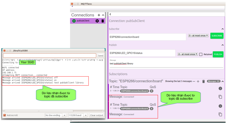
ESP8266MQTTClient
The developer community reviews the ESP8266MQTTClient is more stable and easier to use than the PubSubClient library. The following project is using the ESP8266MQTTClient to control the built-in LED on ESP8266 WiFi Uno by a smartphone app.
-
Step 1 : Download
ESP8266MQTTClientlibrary at github.com/tuanpmt/ESP8266MQTTClient and include it in Arduino. You can also import this library to Arduino IDE by searching the library with the keywordESP8266MQTT, authorTuan PM, version1.3and install it. -
Step 2 : Compile the following source code for ESP8266.
#include <ESP8266MQTTClient.h>
#include <ESP8266WiFi.h>

#define ledPin 16   //Led on board ESP8266 WiFi Uno

MQTTClient mqtt;

const char* ssid = "Your SSID";
const char* password = "Your password";

void setup() {
  Serial.begin(115200);
  pinMode(ledPin, OUTPUT);

  // Turn off LED at the beginning
  digitalWrite(ledPin, HIGH);

  // Configure ESP8266 as a Station and connect to wifi
  WiFi.mode(WIFI_STA);
  WiFi.begin(ssid, password);
  Serial.print("\nConnecting to ");
  Serial.println(ssid);
  while (WiFi.status() != WL_CONNECTED) {
    delay(500);
    Serial.print(".");
  }
  Serial.println("");
  Serial.println("WiFi connected");
  Serial.println("IP address: ");
  Serial.println(WiFi.localIP());

  // Connect to the MQTT server, print the "esp8266/GPIO16" topic's id
  // and subscribe to "hello/esp8266" topic with QoS 0
  mqtt.onConnect([]() {
    Serial.printf("MQTT: Connected\r\n");
    Serial.printf("Subscribe id: %d\r\n", mqtt.subscribe("esp8266/GPIO16", 0));
    mqtt.subscribe("esp8266/GPIO16", 0);
  });

   // Publish a message to subscriber's
  mqtt.onSubscribe([](int sub_id) {
   // Print the subscribed topic's id: "hello/esp8266" and "MQTTlens/test/#"
    Serial.printf("Subscribe topic id: %d ok\r\n", sub_id);

    // Publish "hello app" message to "Broker/app" topic with QoS0 and retain flag 0
    mqtt.publish("Broker/app", "hello app", 0, 0);
  });

  // Handle the received data from subscribed's topic
  mqtt.onData([](String topic, String data, bool cont) {
    Serial.printf("Data received, topic: %s, data: %s\r\n", topic.c_str(), data.c_str());

    // If the received string is 'ON', the LED on ESP8266 WiFI Uno will turn on. And vice versa.
    if (topic == "esp8266/GPIO16" && data[0] == 'o' && data[1] == 'n' && data[2] == '\0') {
      digitalWrite(ledPin, LOW);
      Serial.println("Turn on the led on board");
    } else if (topic == "esp8266/GPIO16" && data[0] == 'o' && data[1] == 'f' && data[2] == 'f' && data[3] == '\0' ) {
      digitalWrite(ledPin, HIGH);
      Serial.println("Turn off the led on board");
    }
  });
  // Begin the MQTT broker "iot.eclipse.org" using WebSocket and listen to client's request at port 80.
  mqtt.begin("ws://iot.eclipse.org:80/ws");
}

void loop() {
  // Initiate MQTT, verify and handle data from the topics,
  // verify the protocol's attributes: keep-a-live packet, QoS packet, topic's id,...
  mqtt.handle();
}
Source Code Explanation
The mqtt variable is in class MQTTClient which is defined in ESP8266MQTTClient library. The library’s functions are explained in the source code.
The setup() function configures ESP8266 as a Station and connects to a wifi network.
The mqtt.onConnect() function subscribes to the topic esp8266/GPIO16.
The mqtt.onSubscribe() publishes the messages to a specified topic Broker/app.
The mqtt.onData() receives, verifies and processes the messages from the subscribed topic. We use a public MQTT Broker iot.eclipse.org and Websocket protocol to listen for MQTT Clients on the default port 80. Transmission using Websocket can reduce the bandwidth and the latency when using MQTT. The detail on Websocket will be introduced later in this book.
In loop() function, we just need to call handle() to initiate and verify the attributes of protocol. The handle() also processes, sends and receives messages from public and subscribed topic.
| For more details on this library, visit github.com/tuanpmt/ESP8266MQTTClient/tree/master/src |
-
Step 3 : Install the app and use it to control LED.
Search on App Store (iOS) or CH Play (Android) and install the IoT Smartconfig app of Tuan PM developer.
Here is an overview of the app:
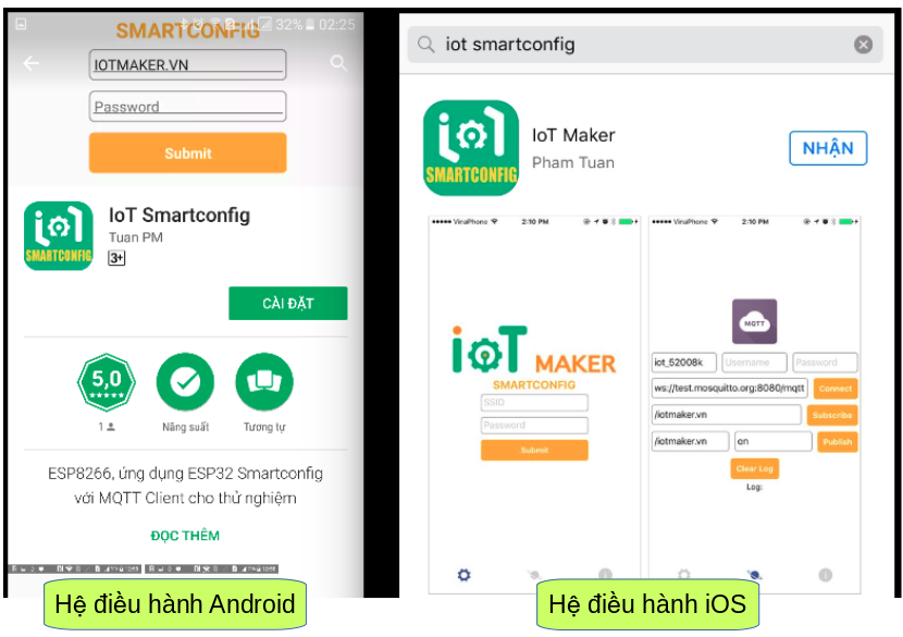
This app can be used with ESP8266 or ESP32. Besides the basic publish/subscribe function of MQTT, this app can use smartconfig to easily configure different networks for ESP8266/ESP32 without recompiling the source code.
Next, swipe to the MQTT section and press the connect button to connect to the MQTT Broker server ws://iot.eclipse.org:80/ws. Subscribe to the topic Broker/app and publish the message to the topic esp8266/GPIO16. If the message is ON, the ESP8266 will light its built-in LED up and vice versa. Other messages to topic Broker/app will be displayed on the app screen. The result is shown below:
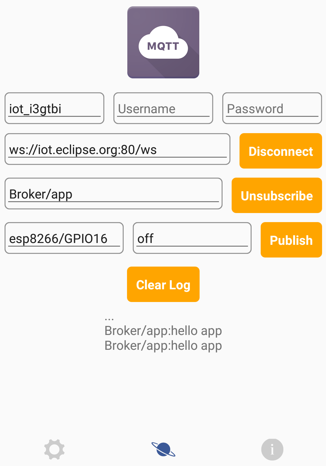
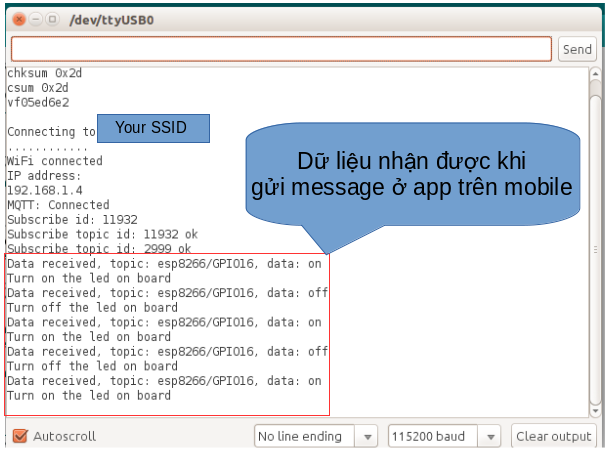
MQTT Broker
At the previous part, we have practised free MQTT Broker services, but we may need to pay for service fee in case of huge application which require high bandwidth and high responsive, additionally data may be attached because of low level security. So, in this article, we will build a MQTT Broker ourself. By setting up a MQTT Broker helps us to use MQTT protocol locally without connection to MQTT Broker services on the internet. The sending, receiving and processing data will be performed in high speed, and securely protect user’s information. However, to set up a MQTT Broker with full features of MQTT protocol require us a good knowledge on MQTT protocol and supported programming languages to build it up. To start up, we will create a simple MQTT Broker by using an exist supported module named Mosca.
MOSCA
Mosca is one of many MQTT Broker server of MQTT protocol. It can be list out other servers such as: HiveMQ, Apache Apollo, Mosquitto, Mongoose. Mosca has some special characters as below:
-
It is a Node.js Broker, written by JavaScript then can build a MQTT Broker, we need Node.js to run. Mosca can embedded into your application if it is written by Node.js
-
Mosce is a multi-transport MQTT Broker, means it supported all publish, subscribe features of other brokers. List of supported publish/subscribe brokers includes: RabbitMQ, Redis, Mosquitto, ZeroMQ. In this article we will create a simple MQTT Broker using Mosca with supporting by
Mongodbdatabase.
Objectives
-
We will create a MQTT Client by ESP8266 and a MQTT Client on the computer by MQTT.js in order to connect to MQTT Broker, subscribing topics and publishing messages.
-
Using Mosca to create MQTT Broker on personal computer to broadcast messages to MQTT Clients.
Performing steps
-
Step 1 : First, we should create a folder to set up a MQTT Broker on local. Navigate to this folder, create package.js file by
npm initcommand and configure project’s information. Next, install mosca module bynpm install mosca --savecommand. To listening connections from clients and saving data about connections and messages content, we need theMongoDB, you can choose Redis, Mosquitto, RabbitMQ, etc. and study about the advantages, disadvantages of these databases. To install MongoDB, we will access to docs.mongodb.com/manual/administration/install-community/, base on your OS, choose the suitable installer package. After installation, we will open port 27017 (dafault port for using mongodb, we can change the port at configuration file of mongodb) to listening to connections from clients viasudo service mongod startcommand. On Linux, connections on system can be checked byNetstatcommand as shown in bellow image:
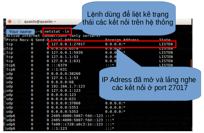
-
Step 2 : Create Javascript file to write the source code for MQTT Broker. Example of serverMosca.js file source code is written bellow:
serverMosca.js file source code
// declare a "mosca" variable to use mosca module's features.
var mosca = require('mosca');
// Using ascoltatore library to publish a message, subscribe to a topic on Broker/Protocol.
var ascoltatore = {
    type: 'mongo',
    url: 'mongodb://localhost:27017/mqtt', // url of MongoDB, server will listen for
    // client's request at localhost:27017
    pubsubCollection: 'ascoltatori', // pubsubCollection: Store MongoDB's message
    mongo: {} // mongo: MongoDB connection setting. Don't use this parameter in this project.
};
var settings = {
    port: 1883, // Server's port
    backend: ascoltatore // "ascoltatore" will be called and executed to initiate connections when a server is created.
};
// Declare "server" variable using mosca.
var server = new mosca.Server(settings);
// This function setups and prints message to console when the Mosca server is ready.
server.on('ready', setup);

function setup() {
    console.log('Mosca server is up and running');
}
// This function prints "Client connected" and client's id to console when a client successfully connects to a server.
server.on('clientConnected', function(client) {
    console.log('client connected', client.id);
});
// This function prints "Client disconnected" and client's id to console when a client disconnects from server.
server.on('clientDisconnected', function(client) {
    console.log('client disconnected', client.id);
});
// This function prints the content of client's message to console in "string" when a client published a message.
server.on('published', function(packet, client) {
    console.log('Published', packet.payload.toString());
});-
Step 3 : Write the source code for ESP8266. For quickly study, we will use ESP8266MQTTClient library’s source code wrote at the previous article. Modify the MQTT Broker’s address from
mqtt.begin("mqtt://iot.eclipse.org:1883");tomqtt.begin("mqtt://your-local-ip:1883");with your-local-ip is the IP address of computer (ex:192.168.1.7), notice that ESP8266 and MQTT Broker must connect to the same local WiFi network. -
Step 4 : Create MQTT Client using MQTT.js. We will create a folder to containing MQTT Client’s files. Similar to step 1, using
npm initto create package.js file and configure project’s information. Next, install mqtt module bynpm install mqtt --savecommand and create the Javascript file to write the content of MQTT Client. Example ofmoscaClient.jsfile source code is shown bellow:
moscaClient.js file source code
// declare a "mqtt" variable to use mqtt module's features.
var mqtt = require('mqtt');
// Connect to port 1883 on 192.168.1.7 using MQTT protocol
var client = mqtt.connect('mqtt://192.168.1.7:1883');
// When a "connect" event arrives at server, client will subscribe the topic "MQTTlens/test/3"
// and publish a message "on" to topic "hello/world" to turn on LED on ESP8266 WiFi Uno.
client.on('connect', function() {
    client.subscribe('Broker/app');
    client.publish('esp8266/GPIO16', 'on');
})
// When a message is delivered to a client, client will convert data in buffer to string
// and print the content to console and close connection.
client.on('message', function(topic, message) {
    // message is Buffer
    console.log(message.toString());
    //client.end();
})
Result
On terminal, navigate to the folder contains moscaServer.js file and launch the server by node moscaServer.js command. Server will start and listen to connections from MQTT Clients. Next, load the program on Arduino to ESP8266, the run the MQTT Client on the computer by node moscaClient.js command. When there are connections, disconnection, publishing a message or subscribing a topic comes from clients then on server side will display the content and information. Terminals display the result as in the figure bellow:
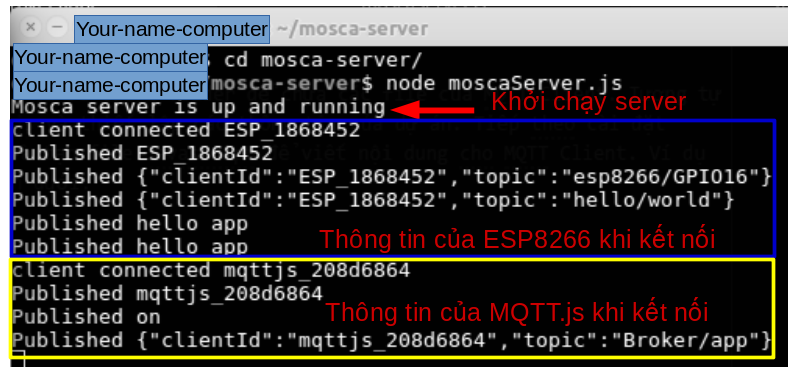
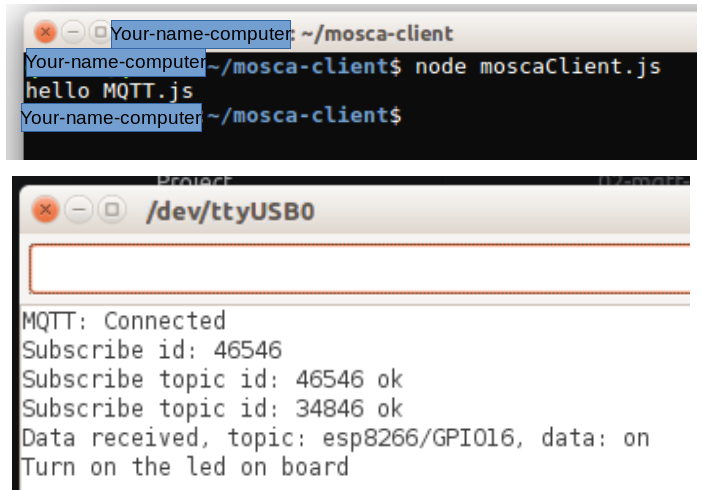
Some MQTT Brokers used for real life products
Mosquitto
Mosquitto is a MQTT Broker written by C programming language. Some special characters of mosquitto is high speed of data transmission and data processing, good stability, widely used and suitable for embedded applications. Suitable for small systems run on local such as Raspberry Pi, moreover Mosquitto also supported TLS/SSL protocols (protocol for server and client authorising purpose, encrypting messages for data protection).
Some disadvantages of mosquitto are difficult to design when using for huge applications and poor of devices authority methods, so the ability of security is not optimized.
EMQ
EMQ (Erlang MQTT Broker) is a MQTT Broker written by Erlang programming language. Advantages of EMQ is high stability, suitable for design huge systems because of easy to expand the application, easy to install. Moreover, EMQ also support a bunch of users authentication methods, developing and features update frequently by developers community. But, disadvantages of this MQTT broker is difficult for new users. Information about EMQ can be seen at emqttd-docs.readthedocs.io/en/latest/#
Summary:
Websocket
WebSokets is an advanced technology that support two-ways communication between client and server by using TCP socket to create a continuous, effective, and low cost connection. Although, it is built for web applications, developers might using it for any kind of projects.
WebSockets is newly introduced in HTML5, allowing bidirectional parallel communications and supported by most of web browsers. Communication is opened via an HTTP request, including special headers that notice Server (supported) switch to WebSocket connection. This connection is maintained then you can send and receive data continuously, no interruption, without any other HTTP header needed.
WebSockets supports most popular web browsers such as: Google Chrome, Microsoft Edge, Internet Explorer, Firefox, Safari and Opera.
Advantages
WebSockets provides the ability on bidirectional connections which is continuously maintained, low latency, easy to communicate between Client and Server. That is why WebSockets is proper for real-time applications, end user do not need to reload their browser to update data like HTTP protocol.
Disadvantages
WebSockets protocol has not been supported by all web browsers already. WebSockets also require to supported by web applications on server.
Using ESP8266 as WebSockets Server
In this article, we will configure application using ESP8266 as a WebSockets Server and browsers as WebSockets Client to update the status of a button, also control an LED on real-time board via web browser.
Requirement
-
Launch a WebServer (WebSockets supported) on ESP8266 MCU.
-
When access to IP address of ESP8266, it will return a HTML file including the content of Javascript that is create WebSockets connection to ESP8266, also listen to data packages from ESP8266 server.
-
When press the button on board, ESP8266 will send the button’s status to web browser to display with checkbox, pressed is checked, not pressed not checked.
-
At the same time, when checkbox clicked on browser it will change status of the LED on ESP8266 board.
Prepare
Install libraries, for more information Install arduino library:
Introduction about ESPAsyncWebServer library
ESPAsyncWebServer is used to configure HTTP server and WebSockets server for ESP8266 module, and process events on server-client.
In order to use ESPAsyncWebserver and run applications, we need to use ESPAsyncTCP.
Javascript snippet code to create Web Socket connection
//Basic steps to create a websocket:

var ws = new WebSocket('ws://domain.com:8000/'); // create a websocket
ws.onopen = function() //
{
   // callback when websocket is successfully opened
};

ws.onmessage = function(evt)
{
    // callback when client received data from server
};
ws.onclose = function() {
    // callback when websocket is closed
};
Embedded HTML file include JS code into ESP8266
<!DOCTYPE HTML>
<html>
<head>
    <title>ESP8266 WebSocket</title>
</head>
<body>
    <div> Webscoket status <span id="status" style="font-weight: bold;"> disconnected </span> </div>
    <div> ESP8266 Button Status <input type="checkbox" id="btn" name="btn" /> </div>
    <div> Control LED <input type="checkbox" id="led" name="led" disabled="true" /> </div>

    <script type="text/javascript">
        var button = document.getElementById('btn');
        var led = document.getElementById('led');
        var url = window.location.host; // return current page's url and port
        var ws = new WebSocket('ws://' + url + '/ws'); // open a websocket at port 8000
        ws.onopen = function() // this function is executed when websocket is opened
        {
            document.getElementById('status').innerHTML = 'Connected';
            led.disabled = false; // until websocket is opened, it is allowed
        };

        ws.onmessage = function(evt) // event triggered when client received data from server
        {
            if(evt.data == 'BTN_PRESSED') {
                button.checked = true;
            } else if(evt.data == 'BTN_RELEASE') {
                button.checked = false;
            }
        };
        ws.onclose = function() { // this function is executed when close websocket
            led.disabled = true;
            document.getElementById('status').innerHTML = 'Disconnected';
        };

        led.onchange = function() { // to turn on/off LED
            var status = 'LED_OFF';
            if (led.checked) {
                status = 'LED_ON';
            }
            ws.send(status)
        }

    </script>
</body>
</html>
Completed program for ESP8266
#include <ESP8266WiFi.h>
#include <ESPAsyncWebServer.h>

const char* ssid = "******";
const char* password = "*********";
const int LED = 16;
const int BTN = 0;

// to embedded HTML code into Arduino program, HTML need to be converted to char

const char index_html[] PROGMEM = ""
"<!DOCTYPE HTML>"
"<html>"
"<head>"
"    <title>ESP8266 WebSocket</title>"
"</head>"
"<body>"
"    <div> Webscoket status <span id=\"status\" style=\"font-weight: bold;\"> disconnected </span> </div>"
"    <div> ESP8266 Button Status <input type=\"checkbox\" id=\"btn\" name=\"btn\" /> </div>"
"    <div> Control LED <input type=\"checkbox\" id=\"led\" name=\"led\" disabled=\"true\" /> </div>"
"    <script type=\"text/javascript\">"
"        var button = document.getElementById('btn');"
"        var led = document.getElementById('led');"
"        var status = document.getElementById('status');"
"        var url = window.location.host;"
"        var ws = new WebSocket('ws://' + url + '/ws');"
"        ws.onopen = function()"
"        {"
"            status.text = 'Connected';"
"            led.disabled = false;"
"        };"
"        ws.onmessage = function(evt)"
"        {"
"            if(evt.data == 'BTN_PRESSED') {"
"                button.checked = true;"
"            } else if(evt.data == 'BTN_RELEASE') {"
"                button.checked = false;"
"            }"
"        };"
"        ws.onclose = function() {"
"            led.disabled = true;"
"            status.text = 'Disconnected';"
"        };"
"        led.onchange = function() {"
"            var status = 'LED_OFF';"
"            if (led.checked) {"
"                status = 'LED_ON';"
"            }"
"            ws.send(status)"
"        }"
"    </script>"
"</body>"
"</html>";

AsyncWebServer server(8000);
AsyncWebSocket ws("/ws");


// Event handler function on Server when browser client trigger an event
void onWsEvent(AsyncWebSocket * server, AsyncWebSocketClient * client, AwsEventType type, void * arg, uint8_t *data, size_t len) {
  if (type == WS_EVT_DATA && len > 0) { // type: type of event received by server. If event comes from websocket, start to process
    data[len] = 0;
    String data_str = String((char*)data); // casting from char to String
    if (data_str == "LED_ON") {
      digitalWrite(LED, 0); // When client trigger event"LED_ON" server turn on the LED
    } else if (data_str == "LED_OFF") {
      digitalWrite(LED, 1); // When client trigger event "LED_OFF" server turn off the LED
    }
  }

}
void setup()
{
  pinMode(LED, OUTPUT);
  pinMode(BTN, INPUT);
  Serial.begin(115200);
  Serial.setDebugOutput(true);
  WiFi.mode(WIFI_AP_STA);
  WiFi.begin(ssid, password);
  if (WiFi.waitForConnectResult() != WL_CONNECTED) {
    Serial.printf("STA: Failed!\n");
    WiFi.disconnect(false);
    delay(1000);
    WiFi.begin(ssid, password);
  }


  ws.onEvent(onWsEvent); // onWsEvent is called
  server.addHandler(&ws);
  server.on("/", HTTP_GET, [](AsyncWebServerRequest * request) {

    request->send_P(200, "text/html", index_html); // return index.html file on browser interface when browser access to server's IP address
  });
    server.begin(); // turn on server

}


void loop()
{
  static bool isPressed = false;
  if (!isPressed && digitalRead(BTN) == 0) { // GPIO0 button pressed
    isPressed = true;
    ws.textAll("BTN_PRESSED");
  } else if (isPressed && digitalRead(BTN)) { // GPIO0 button released
    isPressed = false;
    ws.textAll("BTN_RELEASE");
  }
}
Execute after check the source code:
Result
After completing compile code onto Arduino, open web browser, access into the IP address of ESP8266 returned on Serial Monitor with port configured on server, in this case is 192.168.1.65:8000
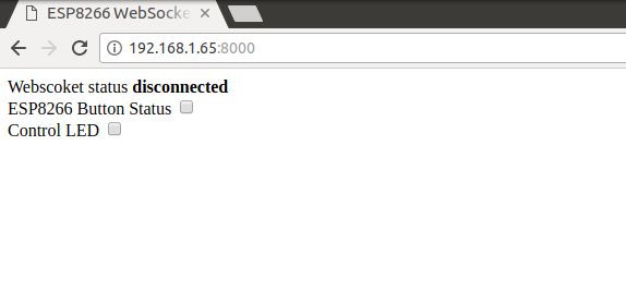
Result video
Using ESP8266 as Websocket Client
In some other applications, we have a WebSockets server to perform real-time tasks such as mobile applications, web applications. In this case, ESP8266 can directly connect to these servers as a WebSocket Client to receive, or send data via WebSockets.
Some famous services use WebSockets such as messenger service Slack, real-time database service Firebase
In this part, we will use Node.js to build a Web server, it plays the roll of a WebSocket server. Which has features on:
-
Provide the file
index.htmlincluding javascript snippet code to create a WebSockets connection between browser and Server, it is like Server Nodejs -
Allow WebSockets connections, from web browsers, or from ESP8266
-
Server will broadcast all data packages from any client to all other clients.
With the features above, you can imagine like this: If web browser windows has WebSockets connections to Server, when a checkbox is checked, it send to server the checkbox status. For example LED_ON, after received, server will broadcast data LED_ON to all other browser (or ESP8266), and all other browser will display checkbox status as checked.
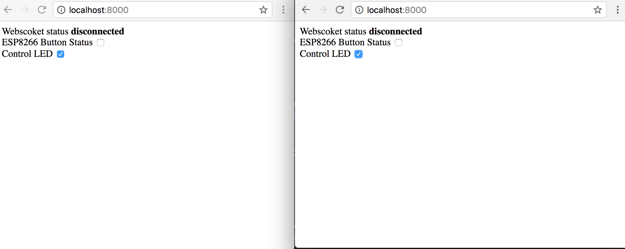
Websocket Client Javascript on web browser
With index.html file which includes Javascript code to create connection to WebSockets, placed in the same directory with server.js
<!DOCTYPE HTML>
<html>
<head>
    <title>ESP8266 WebSocket</title>
</head>
<body>
    <div> Webscoket status <span id="status" style="font-weight: bold;"> disconnected </span> </div>
    <div> ESP8266 Button Status <input type="checkbox" id="btn" name="btn" /> </div>
    <div> Control LED <input type="checkbox" id="led" name="led" disabled="true" /> </div>

    <script type="text/javascript">
        var button = document.getElementById('btn');
        var led = document.getElementById('led');
        var url = window.location.host; // return current page's url and port
        var ws = new WebSocket('ws://' + url + '/ws'); // create a websocket with port 8000
        console.log('connecting...')
        ws.onopen = function() // this function is executed when websocket is opened
        {
            document.getElementById('status').innerHTML = 'Connected';
            led.disabled = false; // until websocket is opened, it is allowed
            console.log('connected...')
        };

        ws.onmessage = function(evt) // event triggered when client received data from server
        {
            console.log(evt.data)
            if(evt.data == 'BTN_PRESSED') {
                button.checked = true;
            } else if(evt.data == 'BTN_RELEASE') {
                button.checked = false;
            } else if(evt.data == 'LED_OFF') {
                led.checked = false;
            } else if(evt.data == 'LED_ON') {
                led.checked = true;
            }
        };
        ws.onclose = function() { // this function is executed when close websocket
            led.disabled = true;
            document.getElementById('status').innerHTML = 'Connected';
        };

        led.onchange = function() { // to turn on/off LED
            var led_status = 'LED_OFF';
            if (led.checked) {
                led_status = 'LED_ON';
            }
            ws.send(led_status)
        }

    </script>
</body>
</html>
Node.js Websocket Server
In this article, we use WebSockets library ws github.com/websockets/ws. You can install by run the command line:
npm install ws
var fs = require('fs');
var url = require('url');
var http = require('http');
var WebSocket = require('ws');


// function to send the response from server side, or receive the request from client
function requestHandler(request, response) {
    fs.readFile('./index.html', function(error, content) {
        response.writeHead(200, {
            'Content-Type': 'text/html'
        });
        response.end(content);
    });

}

// create http server
var server = http.createServer(requestHandler);
var ws = new WebSocket.Server({ server });
var clients = [];

function broadcast(socket, data) {
    console.log(clients.length);
    for(var i=0; i<clients.length; i++) {
        if(clients[i] != socket) {
            clients[i].send(data);
        }
    }
}
ws.on('connection', function(socket, req) {
    clients.push(socket);

    socket.on('message', function(message) {
        console.log('received: %s', message);
        broadcast(socket, message);
    });

    socket.on('close', function() {
        var index = clients.indexOf(socket);
        clients.splice(index, 1);
        console.log('disconnected');
    });
});

server.listen(8000);
console.log('Server listening on port 8000');
ESP8266 Websocket Client
#include <Arduino.h>

#include <ESP8266WiFi.h>
#include <WebSocketsClient.h> //https://github.com/Links2004/arduinoWebSockets
WebSocketsClient webSocket;

const char* ssid = "...";
const char* password = "...";
const int LED = 16;
const int BTN = 0;

void webSocketEvent(WStype_t type, uint8_t * payload, size_t length) {
  switch (type) {
    case WStype_DISCONNECTED:
      Serial.printf("[WSc] Disconnected!\n");
      break;
    case WStype_CONNECTED:
      {
        Serial.printf("[WSc] Connected to url: %s\n",  payload);
      }
      break;
    case WStype_TEXT:
      Serial.printf("[WSc] get text: %s\n", payload);
      if(strcmp((char*)payload, "LED_ON") == 0) {
        digitalWrite(LED, 0); // When client trigger event"LED_ON" server turn on the LED
      } else if(strcmp((char*)payload, "LED_OFF") == 0) {
        digitalWrite(LED, 1); // When client trigger event "LED_OFF" server turn off the LED
      }
      break;
    case WStype_BIN:
      Serial.printf("[WSc] get binary length: %u\n", length);
      break;
  }
}

void setup() {
  pinMode(LED, OUTPUT);
  pinMode(BTN, INPUT);
  Serial.begin(115200);
  Serial.println("ESP8266 Websocket Client");
  WiFi.begin(ssid, password);
  while (WiFi.status() != WL_CONNECTED) {
    delay(500);
    Serial.print(".");
  }

  webSocket.begin("192.168.0.106", 8000);
  webSocket.onEvent(webSocketEvent);

}

void loop() {
  webSocket.loop();
  static bool isPressed = false;
  if (!isPressed && digitalRead(BTN) == 0) { // GPIO0 button pressed
    isPressed = true;
    webSocket.sendTXT("BTN_PRESSED");
  } else if (isPressed && digitalRead(BTN)) { // GPIO0 button released
    isPressed = false;
    webSocket.sendTXT("BTN_RELEASE");
  }
}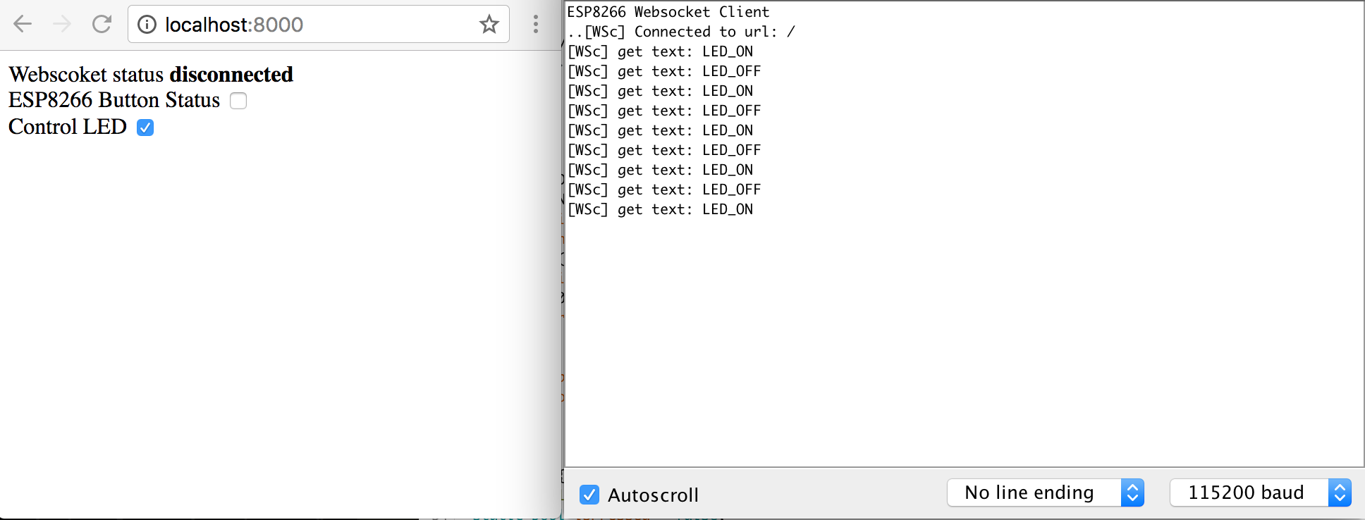
Summary
Using WebSocket protocol has bunch of advantages on two-ways connections, stable and minor latency.
Firmware update over the air (FOTA)
Among nowadays software development and products development processes, partially periodically public the result bring the most effective, products will earlier derive to end user, earlier get user’s feedback, and more reasonable customized. The early public make products poor of features and need to update, and enrich products' quality in the future.
Applications update over the air on mobile phone and PC is already popular. Software applications are updated weekly, monthly… to fix issues, upgrade features.
It is similar with hardware products, features should be updated over the air since the development phase. Beside the easy to update features in the future, issues fixing, system upgrade over the air will save a lot of costs and resources.
In this article, we will study methods to update over the air for ESP8266, how to wireless flash the firmware for module, how ESP8266 can automatically download the firmware, how ESP8266 can automatically boots up an HTTP server to get the web interface then upload firmware onto chip.
Firmware update over the air
Firmware update OTA (Over the Air) is the process of uploading a new firmware onto ESP8266 module instead of using serial ports. This feature is very useful in cases of limited physical connect to ESP Module.
OTA is available on:
-
Arduino IDE
-
Web Browser
-
HTTP Server
Using OTA with Arduino IDE option during development phase, testing, the rest 2 options is suitable for real application deployment, provide OTA update via web or by using HTTP server.
In all cases, OTA supported firmware need to be uploaded the first time via serial ports, if it works fluently, OTA logic applied properly then firmware update OTA is now possible.
There is not security guarantee for the OTA update what can be hacked. It is depends on the development company who ensure the legal and authorised update. When updating is completed, ESP8266 will reboot and execute the new code. Developers must make sure that real applications on module are terminated and restart safely. Bellow content provide additional information about security, and safety for OTA update process.
Security
When ESP8266 is allowed to perform OTA, that means it is wireless connected and be able to update the new Sketch. So, the ability of being attacked is higher and the probability of being flashed another code onto ESP8266 is more than higher. To reduce the risk of being attacked, it need to considering to protect your update with a password, stable fixed different port, etc.
Frequently check features provided by ArduinoOTA library, it can be upgraded the secure ability:
void setPort(uint16_t port);
void setHostname(const char* hostname);
void setPassword(const char* password);
Some secure features are already built-in and do not require any encryption from developers. ArduinoOTA and espota.py use Digest-MD5 to authorise uploading firmware. Simply ensure the integrity of firmware by calculating MD5.
Let’s analyze the risk for your own application and base on your application to decide which features and libraries to execute. If need, consider to effectuate protecting procedure against hacked, for example OTA update only allowed to upload follow specific schedule, activating OTA is only when user press the dedicated button "update", etc.
Safety
OTA procedure consumes resource and bandwidth of ESP8266 when uploaded. After that ESP8266 is restarted and executes an new Sketch. It need to analyze and check the affect of this process to old features and the new Sketch of ESP module.
If ESP is placed far away and controlling some devices, we should take care on slave devices if it is unexpected stop due to update process. So that, we should confirm the normal working status of devices before update process. For example, module is used to control water supplier system in the garden. If during operation process, controlling system is suddenly terminated and valves are opened, then all the garden will be flooded.
Below functions are provided by ArduinoOTA library and used to handle applications during OTA update process or handle if OTA is failed:
void onStart(OTA_CALLBACK(fn));
void onEnd(OTA_CALLBACK(fn));
void onProgress(OTA_CALLBACK_PROGRESS(fn));
void onError(OTA_CALLBACK_ERROR (fn));
Fundamental requirements
Flash memory must has enough space for both the old sketch (operating the system) and the new sketch (OTA update).
Files and EEPROM are also need enough free space.
Function ESP.getFreeSketchSpace(); is used to check the free space for the new sketch.
Update process - memory view
-
The new sketch will be saved in the free space between old sketch and spiff.
-
In the next reboot, “eboot” bootloader checks command lines.
-
New sketch will be copied.
-
New sketch start.
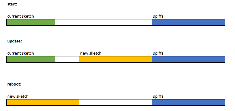
OTA using Arduino IDE
OTA update with Arduino IDE should be done only if:
-
To upload firmware for ESP8266 module via WiFi without serial ports
-
ESP8266 and PC which run Arduino IDE are connected to the same local WiFi network
-
ESP8266 is successfully connected to WiFi network
-
Supported OTA firmware is flashed via serial ports previously
Before start, it is needed to ensure that the latest version of Arduino IDE is installed, including ESP8266 pack for Arduino, and Python 2.7
Step 1: Upload OTA supported firmware via serial ports
Open sample sketch BasicOTA.ino. Open File > Examples > ArduinoOTA.
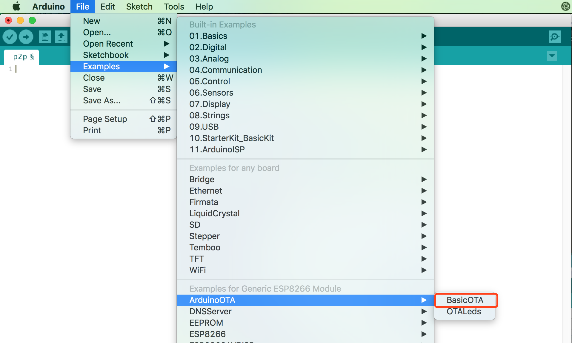
Provide the proper SSID and password of WiFi network for ESP8266 to connect
const char* ssid = "..........";
const char* password = "..........";| Base on IDE’s version and using ESP board, you can see ``Upload Using:`` in menu. This option will not take effect to your choice. This feature is compatible with older OTA versions and be uninstall in platform package version 2.2.0. |
Upload sketch Ctrl+U When completed, open Serial Monitor Ctrl+Shift+M (reference using Arduino IDE Serial Monitor) and check if module is accessed to WiFi or not
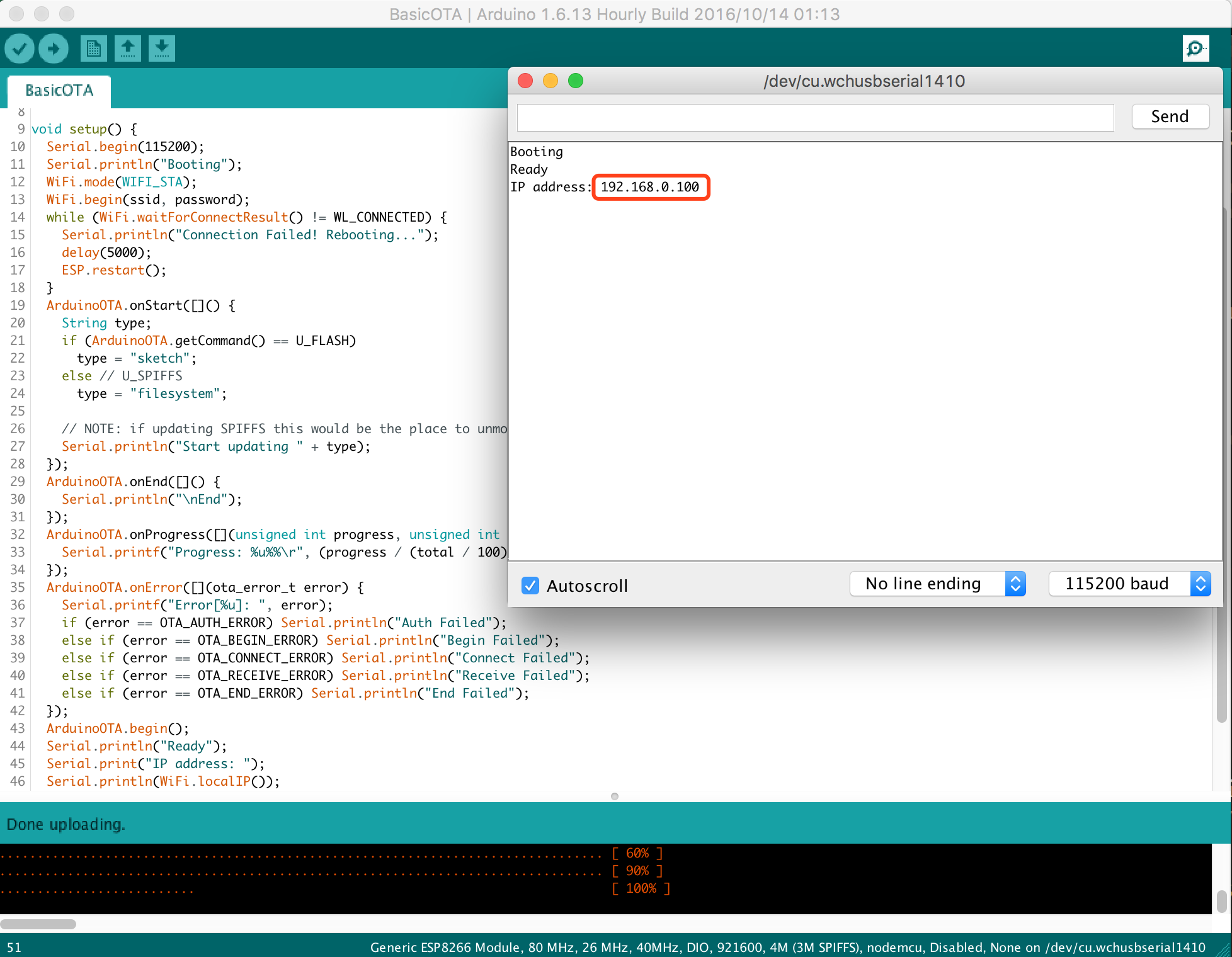
| ESP module should be resetted after complete uploading firmware |
#include <ESP8266WiFi.h>
#include <ESP8266mDNS.h>
#include <WiFiUdp.h>
#include <ArduinoOTA.h>

const char* ssid = "...";
const char* password = "...";

void setup() {
  Serial.begin(115200);
  Serial.println("Booting");
  WiFi.mode(WIFI_STA);
  WiFi.begin(ssid, password);
  while (WiFi.waitForConnectResult() != WL_CONNECTED) {
    Serial.println("Connection Failed! Rebooting...");
    delay(5000);
    ESP.restart();
  }
  ArduinoOTA.onStart([]() {
    String type;
    if (ArduinoOTA.getCommand() == U_FLASH)
      type = "sketch";
    else // U_SPIFFS
      type = "filesystem";

    // NOTE: if updating SPIFFS this would be the place to unmount SPIFFS using SPIFFS.end()
    Serial.println("Start updating " + type);
  });
  ArduinoOTA.onEnd([]() {
    Serial.println("\nEnd");
  });
  ArduinoOTA.onProgress([](unsigned int progress, unsigned int total) {
    Serial.printf("Progress: %u%%\r", (progress / (total / 100)));
  });
  ArduinoOTA.onError([](ota_error_t error) {
    Serial.printf("Error[%u]: ", error);
    if (error == OTA_AUTH_ERROR) Serial.println("Auth Failed");
    else if (error == OTA_BEGIN_ERROR) Serial.println("Begin Failed");
    else if (error == OTA_CONNECT_ERROR) Serial.println("Connect Failed");
    else if (error == OTA_RECEIVE_ERROR) Serial.println("Receive Failed");
    else if (error == OTA_END_ERROR) Serial.println("End Failed");
  });
  ArduinoOTA.setPassword((const char *)"ota-pass");
  ArduinoOTA.begin();
  Serial.println("Ready");
  Serial.print("IP address: ");
  Serial.println(WiFi.localIP());
}

void loop() {
  ArduinoOTA.handle();
}
Step 2: Chose uploading port via OTA
When module is successfully connected to WiFi network, after some seconds, esp8266-ota port will appear on Arduino IDE. Now you can totally remove the serial connection from the board to your computer. Arduino IDE can flash new firmwares via WiFi. chose the port with IP address as shown in the Serial Monitor at the previous step.
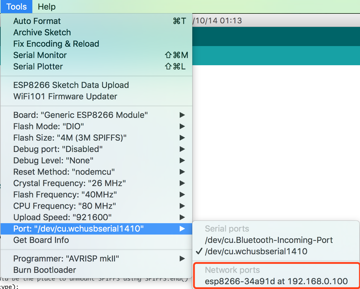
| If OTA port does not appear, you neet to close Arduino IDE and restart. Check the OTA port again. If OTA port still not appears, check the computer firewall and other configurations on router. |
Step 3: Modify new firmware and re-upload via WiFi
After chose the correct OTA flash port, you are totally able to modify the new firmware and re-upload via WiFi, but need to notice that:
-
New firmware must safely keeps the connection to WiFi (wrong-password-update for example)
-
New firmware must contains the OTA initialize and OTA processing like Step 1: Upload OTA supported firmware via serial ports
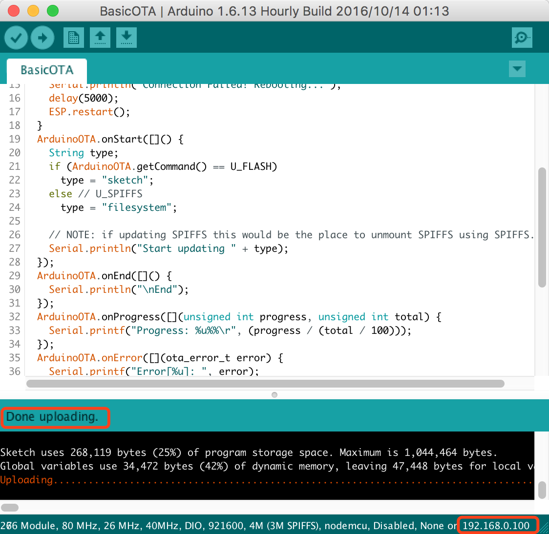
Using password
Protecting OTA uploading process is quite simple. All you need to do is add the bellow code:
ArduinoOTA.setPassword((const char *)"your-password");After that, re-upload the sketch again (using OTA). After completely compile and upload, password requirement window will be shown:
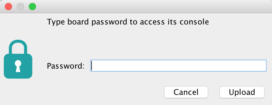
Enter password, if correct, result is the notice Authenticating...OK and uploading process runs normally.
Next uplading times, Arduino IDE remember the password and does not ask again, except you change the OTA password, and the authentication step is not success, Arduino IDE will ask it again.
Keep in mind that password is easy to see, if IDE is not closed after the last uploading time. This can be done by Show verbose ouput during: upload in File > Preferences and upload to module.
Common errors
If OTA update is failed, the first step you need to do is check the error message at Arduino IDE’s Log windows. If it can not help, let’s upload again after check informations of ESP on serial port.
Popular causes of OTA error:
-
There is not enough free space on chip (ESP01 with 512KB flash memory is not enough for OTA).
-
Data zone for SPIFFS is too big, not enough space for firmware, in case you have 4MB Flash, this situation will not occur.
-
Memory zize for firmware is too small, minimum size should be 512KB
-
Do not reset ESP after the first uploading via serial port.
Firmware using Web Browser
When updating firmware using Web Browser, ESP8266 will lunch an HTTP Server, with an uploading form. When access the correct address, you will get an interface to chose binary file, and upload to chip. This is useful if not using Arduino IDE for updating, using the already available browser. Or integrate into an application which you might want to update in the future.
Updating via web browser is done by ESP8266HTTPUpdateServer library and 2 other libraries ESP8266WebServer and ESP8266mDNS for recognizing ESP8266 in the local network.
Implementation
Open sample: File > Examples > ESP8266HTTPUpdateServer > WebUpdater
#include <ESP8266WiFi.h>
#include <WiFiClient.h>
#include <ESP8266WebServer.h>
#include <ESP8266mDNS.h>
#include <ESP8266HTTPUpdateServer.h>

const char* host = "esp8266-webupdate";
const char* ssid = "...";
const char* password = "...";

ESP8266WebServer httpServer(80);
ESP8266HTTPUpdateServer httpUpdater;

void setup(void){

  Serial.begin(115200);
  Serial.println();
  Serial.println("Booting Sketch...");
  WiFi.mode(WIFI_AP_STA);
  WiFi.begin(ssid, password);

  while(WiFi.waitForConnectResult() != WL_CONNECTED){
    WiFi.begin(ssid, password);
    Serial.println("WiFi failed, retrying.");
  }

  MDNS.begin(host);
  httpUpdater.setup(&httpServer);
  httpServer.begin();

  MDNS.addService("http", "tcp", 80);
  Serial.printf("HTTPUpdateServer ready! Open http://%s.local/update in your browser\n", host);
}

void loop(void){
  httpServer.handleClient();
}
Provide the correct SSID, WiFi password you are using, flash firmware WebUpdater onto ESP8266 Select Board ESP8266 WiFi Uno in Arduino IDE and Load the program file into the board using the Arduino IDE
| Notice that the computer should be in the same WiFi network with ESP8266 |
If you can not access to module ESP8266 via serial port, to recognize module’s IP address in LAN, you can run the service mDNS on your computer. This service is already available in MacOS, however, in Linux, you should install Avahi: avahi.org/, and Bonjour for Windows: support.apple.com/downloads/bonjour_for_windows
With mDNS service on the computer, you can easily access to ESP8266 via esp8266-webupdate.local/update
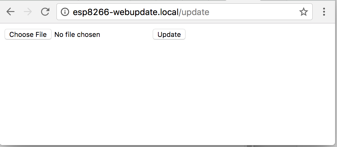
By choosing file and press update, ESP8266 will update the new firmware you upload. This file can be exportd by Sketch > Export compiled Binary, and the .bin file will be placed in the folder of Sketch
If you enter esp8266-webupdate.local/update but it is not affect, let’s change esp8266-webupdate with the new IP address of module (you can find it at modem/router, or Serial Terminal). For example, if module’s IP is 192.168.1.100 then the URL should be 192.168.1.100/update. This method is useful incase of host software which installed at step 1 does not work.
|
If all above step works properly, on web browser and Serial Terminal (if opened) should look like this
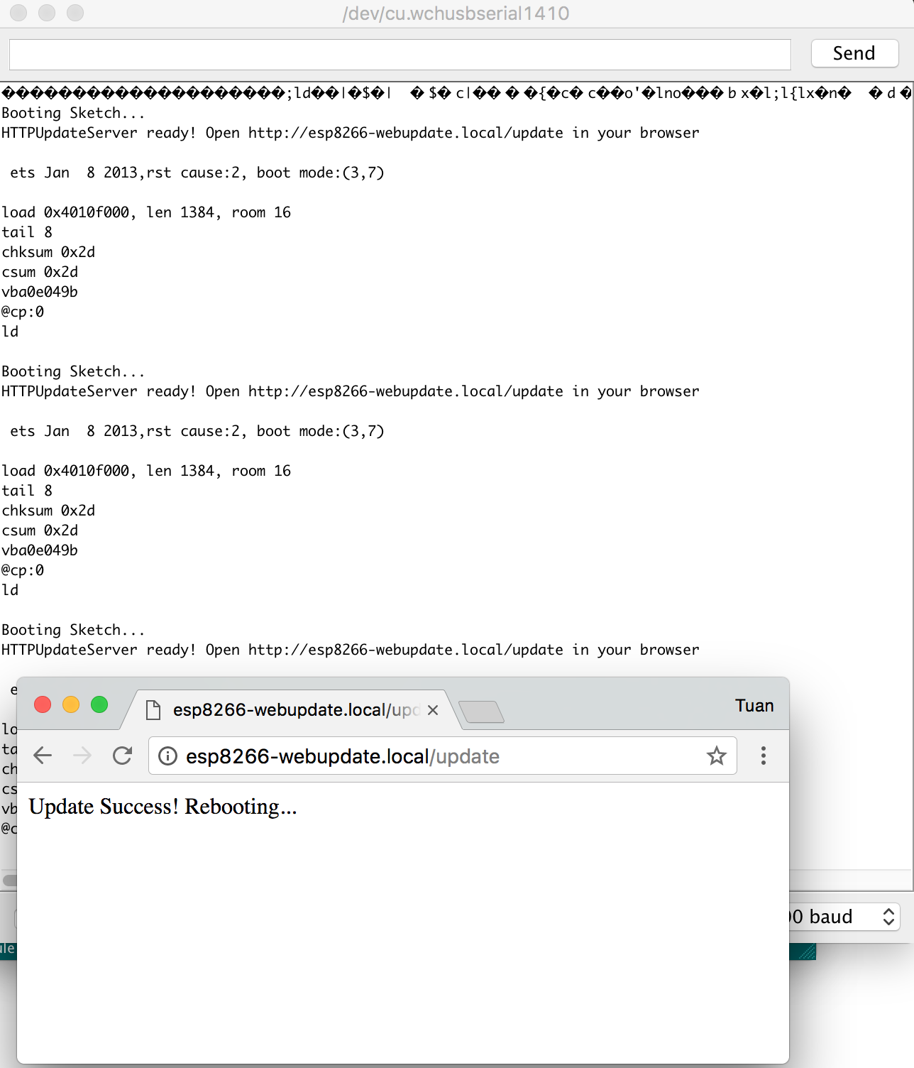
Security
If you include WebUpdater into your product, of course you do not want any one else upload another firmware. Let’s use the method httpUpdater.setup(&httpServer, update_path, update_username, update_password); with parameters username, password which you must enter the correctly to upload the new firmware.
Open the sample: File > Examples > ESP8266HTTPUpdateServer > SecureWebUpdater for details
HTTP Server
With 2 above methods, you can easily update Firmware via local WiFi network. However, when deploy real life applications, we need to update Firmware OTA via Internet, and need a server to stored firmware, and manage all versions.
A common scrip which usually being done is:
-
When ESP8266 start (after an interval of time - 1 day for example), it will connect to server, provide it’s current version
-
When server relize that the current version should be upgraded, it return the new fimrware
-
If current version of ESP8266 is not need to update, it return the 304 code.
In order to do this, we need to perform on both ESP8266 and from server side. Practice for this, we will use Node.js to built a server. You are surely execute this snippet code and assign for domain then access everywhere.
ESP8266 ESPhttpUpdate
By execute ESPhttpUpdate.update("your-domain.com", 8000, "/fimrware.bin");, ESP8266 will automatically connect to server at your-domain.com:8000/fimrware.bin to download the new fimrware. HTTP Status Code:
-
(Code) 200: If the new firmware exists, and the file’s content will be transfered accompanyly after that
-
(Code) 304: Notice that there is no update available.
Snippet code can easily be found at File > Examples > ESPhttpUpdate > httpUpdate
You need to provide SSID, correct WiFi password, execute Select Board ESP8266 WiFi Uno in Arduino IDE and Load the program file into the board using the Arduino IDE
#include <Arduino.h>
#include <ESP8266WiFi.h>
#include <ESP8266HTTPClient.h>
#include <ESP8266httpUpdate.h>

const char* ssid = "...";
const char* password = "...";
const char *currentVersion = "1.0"; (1)
const char *serverUrl = "http://192.168.0.106:8000/firmware.bin"; (2)
void setup() {

  Serial.begin(115200);
  Serial.println();
  Serial.println();
  Serial.print("ESP8266 http update, current version: ");
  Serial.println(currentVersion);

  WiFi.begin(ssid, password);
  while (WiFi.status() != WL_CONNECTED) {
    delay(500);
    Serial.print(".");
  }
  t_httpUpdate_return ret = ESPhttpUpdate.update(serverUrl, currentVersion);
  switch (ret) {
    case HTTP_UPDATE_FAILED:
      Serial.printf("HTTP_UPDATE_FAILD Error (%d): %s", ESPhttpUpdate.getLastError(), ESPhttpUpdate.getLastErrorString().c_str());
      break;

    case HTTP_UPDATE_NO_UPDATES:
      Serial.println("HTTP_UPDATE_NO_UPDATES");
      break;
    case HTTP_UPDATE_OK:
      Serial.println("HTTP_UPDATE_OK");
      break;
  }

}

void loop() {
}| 1 | Your fimrware, assume that you modify as 2.0 and place on server, after that you undo to 1.0 and upload onto board |
| 2 | The path to your firmware, web address, or domain |
Node.js OTA Server
When ESP8266 connected to web server. it provide Header’s information and base on that, server evaluate the fimrware if it is needs to update or not. Headers example
[HTTP_USER_AGENT] => ESP8266-http-Update
[HTTP_X_ESP8266_STA_MAC] => 18:FE:AA:AA:AA:AA
[HTTP_X_ESP8266_AP_MAC] => 1A:FE:AA:AA:AA:AA
[HTTP_X_ESP8266_FREE_SPACE] => 671744
[HTTP_X_ESP8266_SKETCH_SIZE] => 373940
[HTTP_X_ESP8266_SKETCH_MD5] => a56f8ef78a0bebd812f62067daf1408a
[HTTP_X_ESP8266_CHIP_SIZE] => 4194304
[HTTP_X_ESP8266_SDK_VERSION] => 1.3.0
[HTTP_X_ESP8266_VERSION] => 1.0
Base on the knowledge at Server Nodejs, we can build a OTA server using Node.js as below
var fs = require('fs');
var url = require('url');
var http = require('http');
var querystring = require('querystring');
var crypto = require('crypto');
// function send request(response) from server side or receive the request from client
function requestHandler(request, response) {

    // Assume that firmware address http://192.168.1.7:8000/firmware.bin
    var uriData = url.parse(request.url);
    var pathname = uriData.pathname;          // /firmware.bin

    if (pathname == '/firmware.bin') {
        var ver = request.headers['x-esp8266-version'];
        console.log('Client request update, version ', ver);
        if(ver == '1.0') {
            console.log('Send firmware 2.0 to client');
            fs.readFile('./esp8266-firmware-2.0.bin', function(error, content) {
                response.writeHead(200, {
                    'Content-Type': 'binary/octet-stream',
                    'Content-Length': Buffer.byteLength(content),
                    'x-MD5': crypto.createHash('md5').update(content).digest("hex")
                });
                response.end(content);
            });
        } else {
            response.statusCode = 304;
            response.end();
        }
    }
}
var server = http.createServer(requestHandler);
server.listen(8000);
console.log('Server listening on port 8000');
Execute node server.js to start server
When you work with different programing languages, always make sure that data send to client must contains enough header’s information Content-Length and x-MD5
|
You need esp8266-firware-2.0.bin file at folder ESP8266 ESPhttpUpdate compiled with currentVersion = "2.0" which placed at the same folder with server.js file
|
If you follow all above steps, the result should look like this
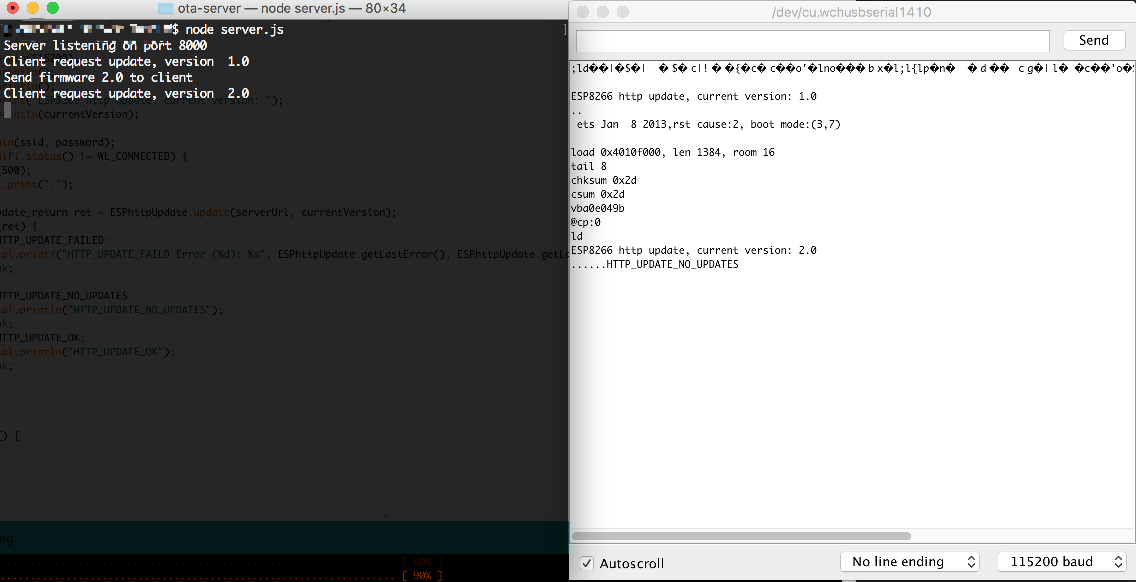
Cheatsheet
Arduino - ESP8266 Cheatsheet
|
|
|
|
|
|
|
|
C - Cheatsheet
|
|
|
|
|
|
The ending
Contributors.
To complete the content of the book also contributed by the following members:
-
Lê Phương Trình - Internship at IoT Maker Vietnam - Telecommunications electronics, Ho Chi Minh City University of Technology University, course 2014.
-
Trần Phúc Vinh - Internship at IoT Maker Vietnam - Electrical engineering, Ho Chi Minh City University of Technology University, course 2014.
And translated to English group:
-
Trần Thiên Hoàng, from Electrical Engineering, International University.
-
Lương Hoài Thiện, from Telecommunications engineering, PFIEV, Ho Chi Minh City University of Technology.
-
Đức Hiếu, manager at NguyenPhong IOT.
And use the community contributions at arduino.esp8266.vn
Thank you
Glad you went with us to the end of this book. The purpose of the book is to help beginners learn about Internet Of Things (IoT) with the basic knowledge and precise effectioncy to study IoT more quickly. Hope the book will come to hand many of you are passionate about the new but very potential technology. Wish you success on the road that you have chosen.
Although tried to finish the best content for the book, however, inevitably the shortcomings. Any suggestions for opening issues at: github.com/tuanpmt/iot-for-beginners-book
Some websites contribute to the community (wish to receive your contribution and contribution to the community of IoT Vietnam in particular as well as the technical community is developing more):
-
1. About ESP8266 with Arduino: arduino.esp8266.vn/
-
2. About ESP32: esp32.vn